How Can We Make Pump and Treat Systems More Energetically Sustainable?


Department of Environment, Land and Infrastructure Engineering, Politecnico di Torino, Corso Duca Degli Abruzzi 24, 10129 Torino, Italy
*
Author to whom correspondence should be addressed.
Water 2020, 12(1), 67; https://doi.org/10.3390/w12010067
Submission received: 4 November 2019
/
Revised: 18 December 2019
/
Accepted: 19 December 2019
/
Published: 23 December 2019
(This article belongs to the Special Issue Groundwater and Soil Remediation)
Abstract
:Pump and treat (P&T) systems are still widely employed for the hydraulic containment of contaminated groundwater despite the fact that their usage is decreasing due to their high operational costs. A way to partially mitigate such costs, both in monetary and environmental terms, is to perform heat exchange (directly or with a heat pump) on the groundwater extracted by these systems, thus providing low-carbon and low-cost heating and/or cooling to buildings or industrial processes. This opportunity should be carefully evaluated in view of preserving (or even improving) the removal efficiency of the remediation process. Therefore, the heat exchange should be placed upstream or downstream of all treatments, or in an intermediate position, depending on the effect of water temperature change on the removal efficiency of each treatment step. This article provides an overview of such effects and is meant to serve as a starting reference for a case-by-case evaluation. Finally, the potentiality of geothermal use of P&T systems is assessed in the Italian contaminated Sites of National Interest (SIN), i.e., the 41 priority contaminated sites in Italy. At least 29 of these sites use pumping wells as hydraulic barriers or P&T systems. The total discharge rate treated by these plants exceeds 7000 m3/h and can potentially provide about 33 MW of heating and/or cooling power.
1. Introduction
The economic and environmental sustainability of subsurface remediation has largely become an acknowledged issue as most widely applied techniques, despite their efficacy, are far from being optimized in terms of energy demand and/or use of “green” chemicals [1]. Pump and treat (P&T) systems are among the oldest and most commonly adopted methods to address groundwater contamination [2]. Groundwater is abstracted from pumping wells that serve as a hydraulic barrier for capturing contaminated fronts, thus stopping contaminant propagation, and the abstracted water undergoes chemical, physical and/or biological processes to remove dissolved contaminants [3]. After the decontamination treatment, water is generally disposed into surface water bodies, reused in industrial processes or reinjected into the same aquifer. P&T systems are therefore an on-site treatment. Despite the relative ease of design and high degree of success, P&T systems have numerous disadvantages, including the extended average duration of the treatment (from several years to some decades, particularly in the case of very heterogeneous aquifers, and contamination due to poorly soluble compounds), the inability to target the contamination source, the necessity to abstract the contaminated water for treatment, the high energy demand and the associated costs.
Despite the increasing use of in situ remediation techniques [4], many P&T systems are still installed and operating all over the world, either as the only remediation intervention implemented at a contaminated site, or for plume control in association with other technologies. According to Pobodnik and Horst [5], an estimate of P&T systems operating in USA in 1997 was 45,508 treating plants on 217,176 contaminated sites (around 21% of the total). More recently, in 2012, Patyn and Lookman [6] reported that P&T is adopted in over half of the 5000 subsurface remediation projects carried out in Flanders (Belgium) since 1995. As discussed later, most of the 41 priority contaminated sites in Italy (SIN, National Interest Sites) have at least one P&T system, which has been in operation for a long time (in some cases more than 10 years).
Because a huge number of P&T systems are currently active and are expected to remain in operation for several years, and because the time scales of this technique are very long, their overall environmental and economic sustainability could potentially be improved by exploiting the energetic potential of the extracted water. The extracted water can be used for heat exchange, directly or through a heat pump, to provide heating and/or cooling to buildings or industrial processes located close to the treatment plants. The thermal use of P&T systems can lead to a partial recovery of their maintenance costs and reduce the overall carbon footprint of the remediation process. This idea was first proposed by Podobnik and Horst (1998, [5]), who performed a large-scale assessment of the feasibility of geothermal exploitation of P&T in US Superfund Sites. The authors concluded that the applicability of groundwater heat pumps (GWHPs) to existing P&T systems mostly depends on the flow rate abstracted, on the foreseen duration of pumping, and on possible uses available nearby. More recently, Potter (2015, [7]) proposed coupling shallow geothermal energy with brownfield remediation, in particular exploiting P&T systems as open-loop geothermal systems or, in case excavations are necessary (e.g., to remove leaking underground storage tanks), installing closed-loop geothermal heat collectors.
While the geothermal exploitation of P&T systems is still at an early stage, the mining sector offers several examples of pumped groundwater thermal use, especially for building and district heating systems, which reduces the overall environmental costs of such operations. Farr et al. (2016) [8] reported that, so far, 16 GWHP systems have been installed in flooded mines in Europe and USA, with the first applications dating back to the early 1980s. System capacities range between 18 and 700 kW, and depths range between 65 and 600 m below ground level. Peralta Ramos et al. (2015, [9]) reviewed the GWHP systems installed in 18 abandoned mines, with an overall heating capacity of 18 to 40,000 kW per each installation. Bailey et al. (2016, [10]) identified 64 former coal mining sites in the UK where the dewatering systems, installed to mitigate flooding and associated spreading of pollutants, can also be used for thermal purposes. Flooded mines are widespread across Europe [11], and hence this solution has good potential for future expansion.
The references and the experiences described above highlight the opportunity of using continuous pumping systems such as P&T to produce renewable heating and cooling. In this paper, we provide a preliminary evaluation of the potential of P&T systems for thermal exploitation, discussing the possible (both negative and positive) interactions with the most commonly adopted water treatment processes. We also propose an overview of the 41 major contaminated sites in Italy, identifying active and foreseen P&T systems to assess their potential for renewable heat.
2. Technical Feasibility of Geothermal P&T Systems
Shallow geothermal systems can be implemented with a closed-loop configuration, based on the circulation of a heat carrier fluid inside a closed pipe loop buried into the ground, or with an open-loop configuration, where the heat is exchanged directly with groundwater abstracted by a water well, and usually reinjected by another well into the same aquifer [12].
Clearly, a P&T system can be adapted to work as an open-loop shallow geothermal system. A major difference with the other open-loop shallow geothermal systems lies in the fact that water from P&T systems is often not re-injected in the subsurface, but rather discharged in surface water bodies or in municipal water treatment plants. The choice between discharge in surface water bodies, wastewater collection systems, or re-injection depends on the water quality standard reached after treatment, and on national legislation. Reinjection into the subsurface requires an evaluation of groundwater thermal alteration, which can influence groundwater quality as well [13].
In view of the implementation of P&T system geothermal exploitation, a key design issue is the type of heat exploitation (for heating, cooling, or both) and the position of the heat exchange (before, after, or in the middle of the groundwater treatment train), as discussed in Section 2.1. The heat exchange causes a temperature variation of the abstracted groundwater (reduction, if used for heating, and vice versa) which may impact the efficiency of the treatment processes. In addition, the heat pump efficiency is influenced by the water temperature at the heat exchanger inlet, which, in turn, depends on the position where the heat exchange is performed. The heat pump and water treatment efficiency are therefore the most influential factors to drive the setup choice, with the obvious priority given to water treatment. These aspects are discussed in Section 2.2.
2.1. Technical Solutions for the Geothermal Exploitation of P&T Systems
The thermal power (kW), exchangeable with the groundwater extracted from a pumping well, applying a temperature difference between abstracted and disposed water, is equal to:
where (m3/h) is the flow rate and is the thermal capacity of water (1.16 kWh·m−3K−1).
The temperature of abstracted water depends on several factors, among which the most important are the local climate and the depth to the water table. At depths of a few meters to a few tens of meters (typical of the great majority of contaminated aquifers), the groundwater temperature is close to the yearly average air temperature, and is almost constant through the year, with possible seasonal oscillations of a few degrees when the aquifer is very shallow (i.e., a few meters of depth) or in proximity to rivers and lakes. Urban heat islands and global warming trends also impact groundwater temperatures, as highlighted by recent studies such as [14,15]. Shallow geothermal installations upstream of the P&T may impact the groundwater temperature, propagating the so-called thermal plumes through advection, dispersion and, to a lesser extent, conduction [16,17]. A further possible alteration is represented by thermal recycling, which occurs when part of the reinjected water returns to the abstraction well [18,19]. On the other hand, groundwater contamination or remediation activities do not have a significant impact on groundwater temperature, except for those specific cases where subsurface heating is the key mechanism of the remediation process itself (e.g., steam injection, air sparging with heated air, etc.) or is an expected side effect of the applied remediation approach (e.g., in situ chemical oxidation (ISCO)).
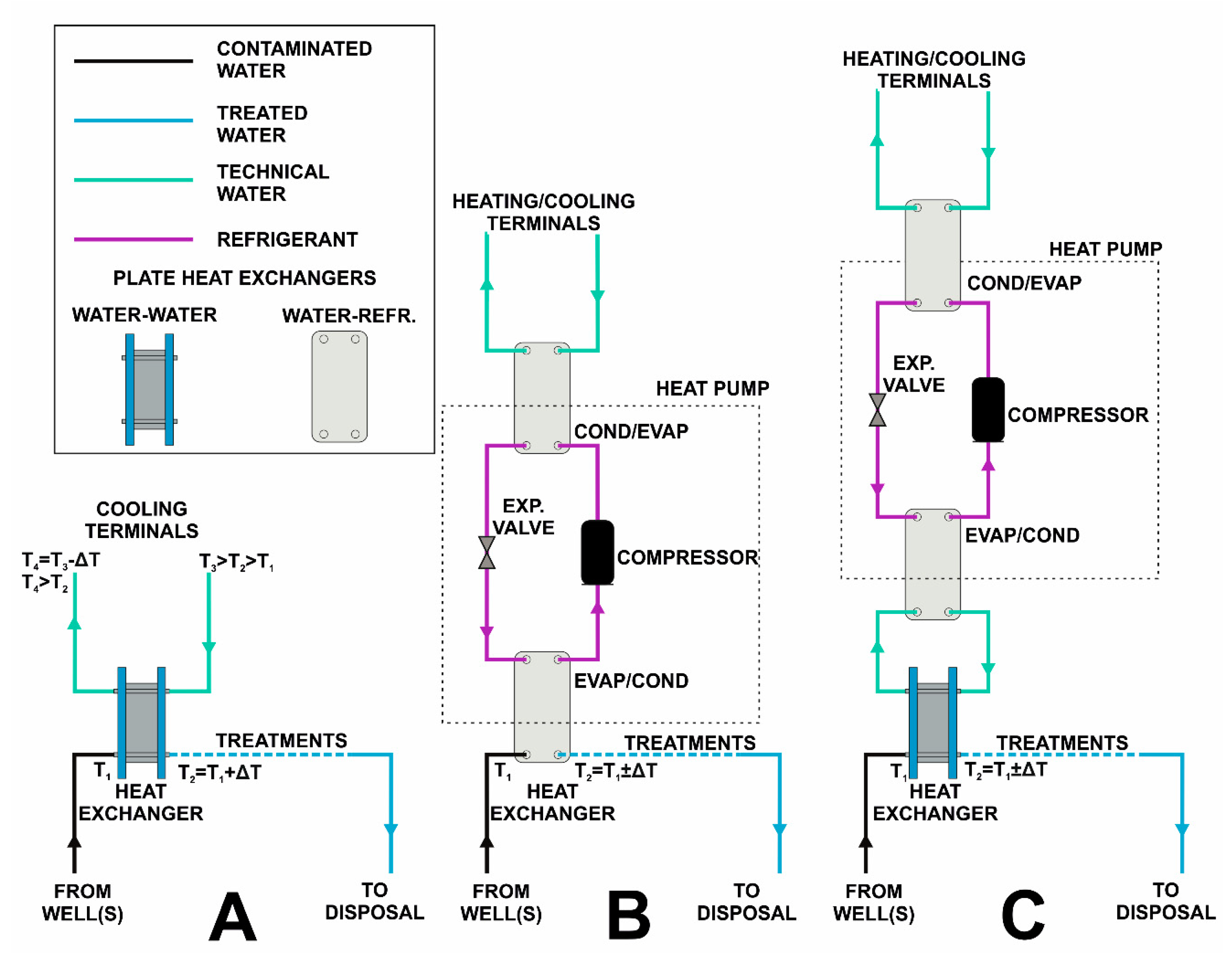
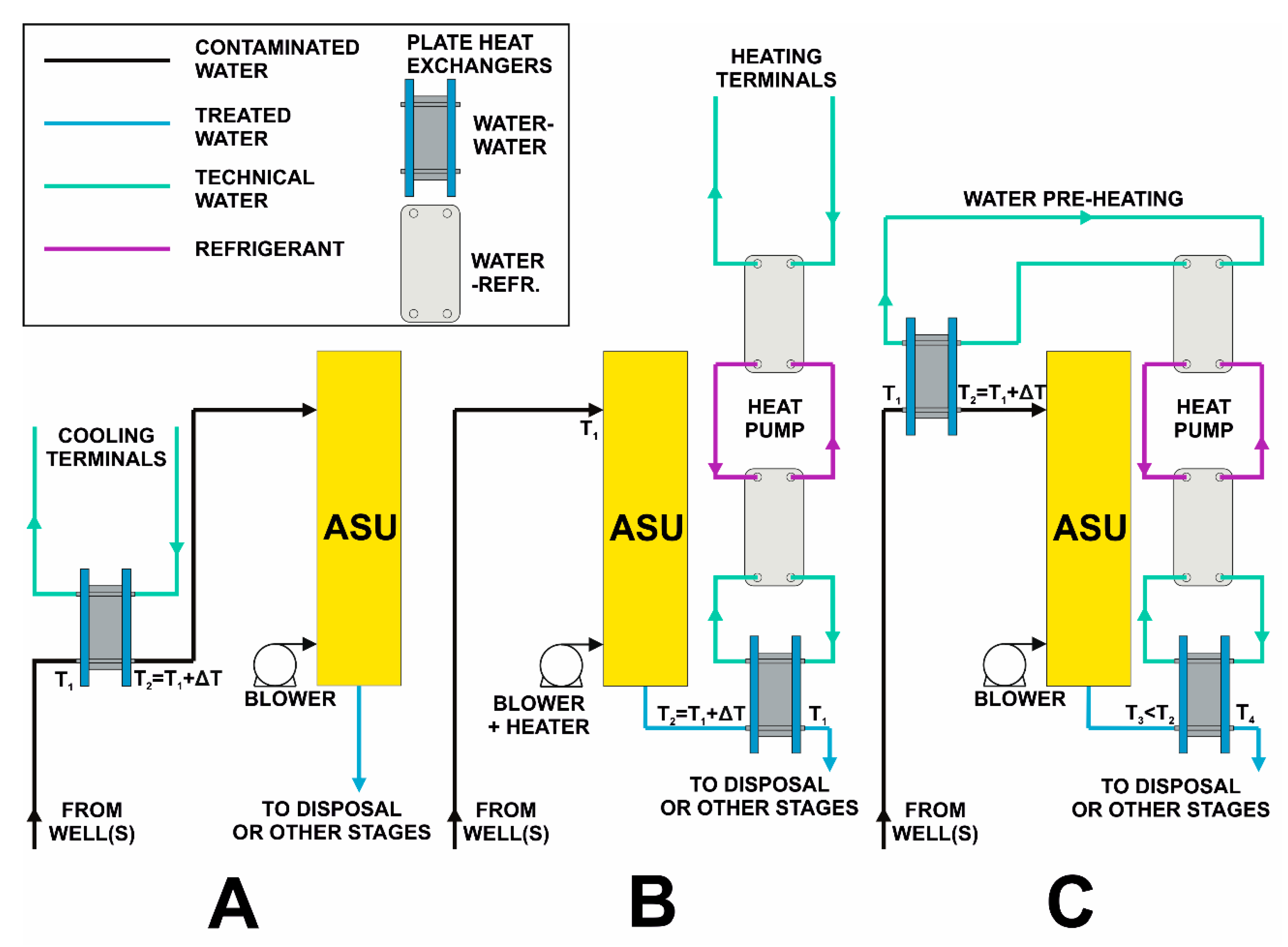
Heat exchange with the groundwater may be direct or mediated by a heat pump (Figure 1). A direct heat exchange (Figure 1A) is possible only for cooling, and only with a hydraulic loop operating at a temperature sufficiently higher than the groundwater. Examples of these cases are radiant panels for building cooling (which generally operate at a minimum temperature of about 15–20 °C to avoid the condensation of air moisture at typical indoor setpoints, i.e., 24–26 °C) and industrial cooling processes (e.g., condensation of turbines). The use of contaminated groundwater for this purpose does not pose severe concerns, except those related to the chemical compatibility of the materials expected to come in contact with the water. Problems tend to arise in the presence of volatile compounds that can evaporate during heat exchange and form a gas phase. Conversely, the formation of precipitates in the abstracted water can be expected if groundwater is exposed to ambient air. All these issues must be foreseen while designing the cooling system, and materials must be carefully selected.
The use of abstracted groundwater for heating (e.g., building heating or hot water production), for cooling with low-temperature terminals (e.g., fan coils) and for refrigeration requires the use of heat pumps (Figure 1B,C). If the contaminated groundwater is circulated directly in the heat pump circuit (Figure 1B), an even more careful evaluation should be made on water quality to avoid corrosion or clogging of the heat pump internal circuits, and in particular of the heat exchanger between the hydraulic circuits of the groundwater and the heat pump’s refrigerant. The literature [20,21] provides references on threshold parameter values for which the installation of an intermediate heat exchanger (Figure 1C) is recommended to preserve the heat pump and to ease maintenance operations (scaling removal, cleaning, and replacement). In general, it is advised to use such an intermediate heat exchange because of the variable quality of abstracted groundwater, and the risk of formation of precipitates or vapor phase. As an alternative, the heat exchange between the groundwater and the heat pump could be placed one or more pre-treatments downstream, removing the contaminants of higher concern for the integrity of heat exchangers. Appendix B.1 presents some examples of how a P&T can be used for heating and cooling buildings and the related benefits in terms of energy saving.
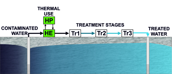
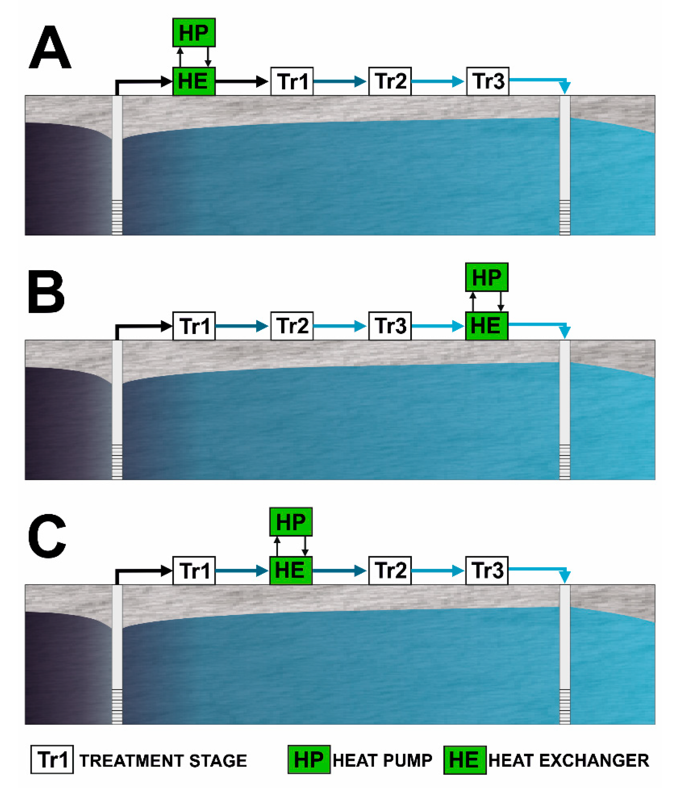
Besides the configuration of the heat exchanger and eventual heat pump, the position of the heat exchanger in the train of water treatment processes is the other key design issue. As shown in Figure 2, three options are available for placing the heat exchanger, namely (A) an upstream configuration, when the heat exchange is placed before all treatment stages, (i.e., immediately after the pumping wells), (B) a downstream configuration, when the heat exchanger is placed after all treatment stages (i.e., upstream of the water disposal), and (C) an intermediate configuration, when the heat exchange is placed between two different treatment stages. The first option presents the major advantage of providing groundwater at an unaltered temperature, thus ensuring the possibility of using it for free cooling (Figure 1A), or, if a heat pump is used (Figure 1B,C), of achieving the highest Coefficent Of Performance (COP) compared to the two other configurations (Figure 2B,C).
Indeed, the outdoor exposition of abstracted groundwater throughout the treatment stages results in temperature variations, which are likely to be unfavorable for the foreseen use and result in lower values of the COP or, in case of cooling systems, of the Energy Efficiency Ratio (EER).
Even though the efficiency of the heat pump is a key element in the evaluation of the P&T potential for energetic exploitation, it is definitely not the only factor in play. As discussed above, physio-chemical and chemical parameters (pH, total dissolved solids, presence of volatile compounds, etc.) of contaminated water may be potentially critical for the heat exchanger; consequently, it can be more convenient to locate the heat exchange after some preliminary water treatments. When an interaction of the contaminants with the heat exchanger is suspected (e.g., contaminants aggressive to the materials of the heat exchanger, or formation of precipitates), it is preferable to adopt a downstream configuration (Figure 2C), even though this may decrease the efficiency of the heat exchange itself. Similarly, a downstream configuration is preferable when the variation of water temperature associated to heat exchange can negatively affect the efficiency of certain treatments. Conversely, an upstream (Figure 2A) or an intermediate (Figure 2B) configuration is to be preferred when the heat exchange can improve the efficiency of all or certain treatments. Although the temperature changes associated with heat pumps are generally in the order of only a few degrees, the economic benefit or damage following the variation of the treatment efficiency could exceed the economic benefit of the thermal use of groundwater. In addition, some treatments require water to be heated, and such heat can partly be recovered with heat pumps placed at the treatment stage outlet.
2.2. Expected Impacts on Water Treatment Processes
In water treatment plants associated with P&T systems, according to the United States Environmental Protection Agency (EPA) [22], chlorinated solvents are the most commonly remediated contaminants in the Superfund sites of US, being treated in 56 of 88 P&T systems (63%) installed; metals (As, Cd, Cr, etc.) are treated in 22 systems (25%), Benzene, Toluene, Ethylbenzene and Xylene (BTEX) in 19 systems (22%), and Polycyclic Aromatic Hydrocarbons (PAHs) in 17 P&T systems (19%). The sum of shares reported exceeds 100% as P&T systems often treat more than one contaminant, with more than one treatment stage. Regarding treatments, the same report shows that carbon absorption is the most used one (56%), followed by air stripping (47%), filtration (35%), metals precipitation (25%), biological treatment (9%), ion exchange (7%), and UV oxidation (5%). Other treatments that may be applied in P&T systems include chemical oxidation, coagulation, distillation, electrochemical, evaporation, filtration, flotation, gravity separation, ion exchange, membrane separation, neutralization, reduction, steam stripping, ozone (EPA, 1996 [23]). The applicability of these techniques to different contaminant types is summarized in Table A1.
Evaluating the effects of temperature variations on the efficiency of water treatments is a difficult task, yet some guidance can be found in the literature.
Sorption, especially on activated carbon, is the most commonly adopted treatment for organic contaminants. Polluted groundwater is pumped into vessels containing the material (sorbent) onto which the dissolved contaminants are adsorbed and, once the contaminant concentration in the outflow exceeds a certain threshold, the sorbent must be regenerated/substituted [23]. The efficiency of a sorbent is expressed by the adsorption isotherms, i.e., the curves describing the correlation between the contaminant concentration in the fluid phase (contaminated groundwater) and in the solid phase (sorbent) at different water temperatures. In general, the adsorption of a contaminant onto an adsorbent is more efficient at higher water temperatures if the process is endothermic, and at lower water temperatures if it is exothermic. Scientific literature in this field reports numerous laboratory test results with different sorbents (activated carbon, wooden charcoal, cashew nutshell, etc.) and different contaminants (benzene, phenols, heavy metals, etc.) highlighting a detrimental [24,25,26,27,28,29,30,31,32,33] or beneficial effect [34,35] of a temperature increase. Based on data reported in these references, the expected increase (or decrease) of absorption capacity (i.e., contaminant mass per unit sorbent mass) is in the order of a few points per cent within the typical temperature variations of geothermal heat pumps (ΔT = 3–7 °C).
The air stripping process is typically used for volatile organic compounds (VOCs). The most common configuration is a packed tower where contaminated water is nebulized and air is supplied counter-current to the water flow, thus stripping volatile contaminants, which are then removed from the air phase with sorption or catalytic oxidation [23]. The effectiveness of air stripping of Volatile Organic Compounds (VOCs) strongly increases with water and air temperature [36,37], thanks to the increase of Henry’s constant, which could be evaluated using reference parameter values from the literature [38,39]. Based on this consideration, it is possible to implement three different heat uses (Figure 3), namely: (A) heat discharge into contaminated water as a pre-heating before the air stripping treatment, thus avoiding (or reducing) any water heating to improve the stripping process; (B) heat recovery after the treatment, if water pre-heating is required for air stripping; (C) implementation of both heat exchanges through a heat pump, i.e., extracting heat from the effluent of the stripping column (connected to the heat pump evaporator) to pre-heat groundwater before the air stripping. A further necessary consideration is the foreseen operating lifetime, as air stripping can often be used in the early stage of a P&T remediation, being replaced by other techniques (such as sorption) as VOC concentrations are reduced [40].
Biological treatments use microorganisms to oxidize groundwater organic pollutants to inorganic species, or less toxic intermediates. Several technological solutions are available with this aim [3,41] and, within the operating limits of the specific bacterial communities (psychrophilic, mesophilic, thermophilic), biological treatments generally improve their efficiency at higher temperatures, and hence groundwater can conveniently be used for cooling purposes upstream of the water treatment plant.
3. Potential Application to the Italian Contaminated Sites of National Interest (SIN)
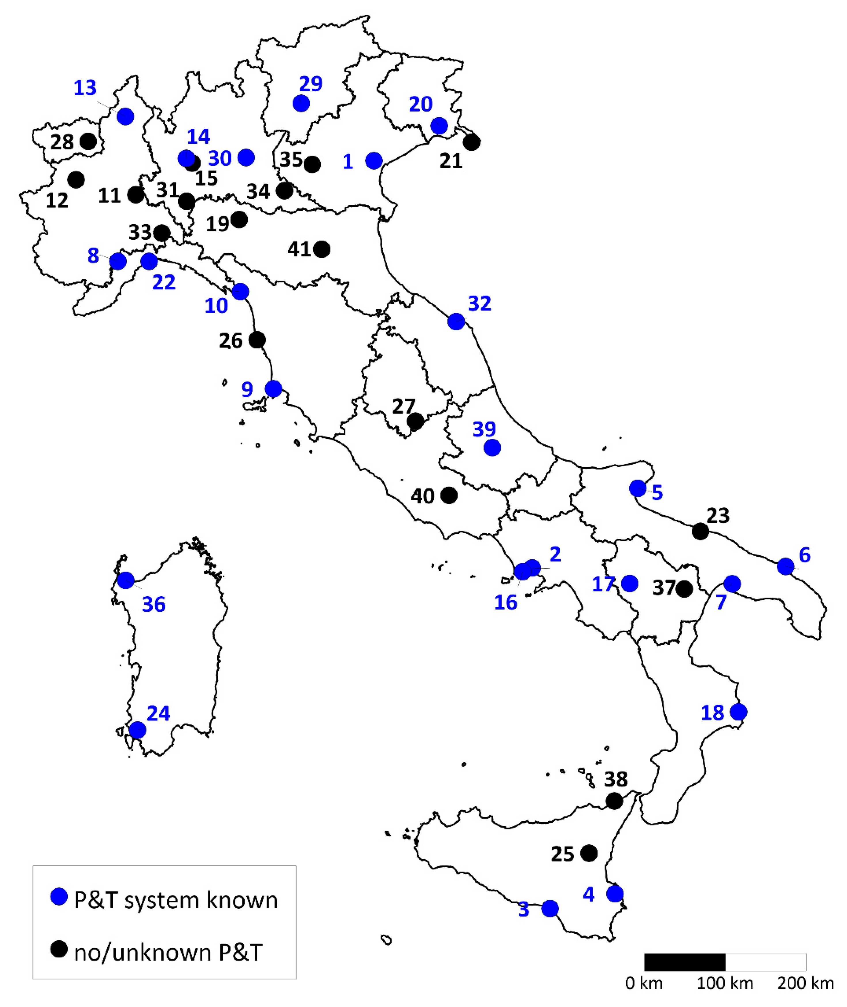
Italy counts more than 4300 contaminated sites (Beretta, 2015 [42]), among which 41 are designated as “Siti di Interesse Nazionale (SIN)” (contaminated Sites of National Interest) (Figure 4) and, according to the Italian law, their management is entrusted to national authorities (ISPRA 2018 [43]).
SINs are mostly large industrial districts with complex contamination and most of the expense for SINs remediation is related to the operation of P&T systems [42]. Up until 2009, an investment of 604 M€ was made to contain and treat contaminated groundwater in 17 SINs; of that amount, 248 M€ were invested to install P&T systems that treat 45 Mm3 per year at an average operational cost of 2.40 €/m3 [44].
The great importance of P&T systems in large site remediation is confirmed by our data retrieved from SINs, which are synthesized in Table A2. P&T systems are installed in 29 SINs (out of the total number of 41) and a new installation is foreseen in three other sites. Most of the sites where P&T systems are not present nor foreseen are contaminated by asbestos (Casale Monferrato, Balangero, Fibronit Bari, Biancavilla, Emarese, Broni and Bologna), to which this remediation technique is not applicable.
Statistics on flow rates extracted and treated were found for 23 sites, with a total flow rate of 7051 m3/h (1959 L/s, detailed data reported in Table 1). More than half of the total flow rate is concentrated in the four largest plants: Brescia Caffaro (1400 m3/h), Pieve Vergonte (1250 m3/h), Priolo (600 m3/h), and Cengio/Saliceto (600 m3/h). According to Equation (1) and hypothesizing a temperature difference , such as in Bailey et al. (2016, [10]), the total potential for heating/cooling is 32.72 MW at the evaporator and condenser side, respectively (see Table 1). Such thermal power is slightly different from the one delivered to the demand side, which depends on the COP (for heating) or the EER (for cooling). For example, assuming the seasonal average value of the COP (SCOP) equal to 5.79 (see Appendix B.1), the heating power would be 38.36 MW; on the other hand, the cooling power with Seasonal EER (SEER) equal to 5.84 (see Appendix B.1) would be 27.12 MW. As a term of comparison, this value slightly exceeds the sum of the two largest groundwater heat pumps in Italy (15 MW each), which have been installed in two district heating power stations in Milano [45].
The energy potentially delivered by these systems was estimated by calculating the full-load equivalent hours (FLEH) in heating and cooling mode using the method proposed by Papakostas et al. (2009, [46]). The input time series of air temperature were retrieved from the MERRA database [47,48], using the 1st and the 99th percentile values as design heating and cooling temperatures, respectively. An indoor balance temperature of 16 °C in heating mode and 20 °C in cooling mode was set. With the FLEH values reported in Table 1, a total potential greenhouse gas (GHG) emission of 13,378 tons CO2eq was estimated compared to the one that covered the same heating and cooling demand with a gas boiler and an air-source chiller, respectively. Input data for the GHG emission factors were taken from Casasso and Sethi (2019, [49]), while the heat pump efficiencies (SCOP = 5.79, SEER = 5.84 for the geothermal heat pump and SEER = 4.26 for the air-source chiller) were taken from the Carrier technical catalogue ([50], further details in Appendix B). The heat pump SCOP and SEER values were assumed for a groundwater temperature of 10 °C at the inlet and 7 °C at the outlet of the evaporator (heating) or condenser (cooling). Groundwater temperatures in the examined sites were deemed to range between 8 °C and 18 °C, based on climate data (yearly average air temperature) and on available groundwater temperatures data [51,52]. Assuming a SCOP/SEER variability of 0.06 per each degree of groundwater temperature (as made in Appendix B.1 and Appendix B.2), the estimate of avoided GHG emission reported in Table 1 would vary by less than 1%.
According to Podobnik and Horst (1998, [5]), four criteria must be fulfilled for the geothermal use of a P&T system, namely (i) a flow rate exceeding 100 gpm (about 20 m3/h), (ii) continuous pumping, (iii) potential users within a radius of 1300 ft (about 400 m), and (iv) at least 10 years of residual foreseen operation. Based on data reported on Table 1, 21 sites fulfill the first criterion on the minimum flow rate, with a potential thermal power between 167 kW and 6496 kW. No information is available on the pumping schedule, but a continuous operation (with eventual seasonal oscillations in the discharge rate) can be reasonably assumed, as P&T systems are generally used for plume control. Concerning the third criterion, possible uses are available within a radius of 400 m from P&T systems in all considered sites. In particular, the largest of such systems (Brescia Caffaro) is located close to the district heating network of Brescia, to which it could provide 6.5 MW, i.e., about 1% of the total power [53].
Finally, the operating lifetime of a P&T system typically exceeds 10 years. For example, P&T in the Brescia Caffaro site has been active since 2004 and in Cengio, since 2006 [54]. Among the four cited criteria, the operating lifetime is likely to be the least important, since the geothermal exploitation of a P&T system could be possible even after the need for water treatment ends. Moreover, at the beginning of the operation of P&T systems (e.g., the first 5 years), it is possible for treatment types to change depending on the operating conditions as pointed out by EPA (2005, [40]). For this reason, the opportunity of using treated water for thermal exchange should be evaluated after a final decision is made on the water treatment train.
4. Conclusions
Despite remediation of contaminated sites shifting to in-situ methods, the P&T technique is still largely used for hydraulic confinement and water clean-up. Long-term pumping, well maintenance and water treatments represent the highest costs associated with P&T systems, and large quantities of energy and/or chemicals are needed to perform groundwater remediation with such a method. To reduce the operation and maintenance costs of such systems, it is possible to exploit the pumped groundwater as a renewable energy resource for the heating and cooling of buildings by means of a water–water heat pump (groundwater heat pump, GWHP), or by using a heat exchanger to inject heat down into the groundwater (free cooling).
The heat exchanger can be placed upstream or downstream of all treatment stages, or between two stages, depending on the effect (positive or negative) of the induced temperature variation on the efficiency of the treatment steps downstream of the heat exchanger.
A literature review on the main water treatment technologies highlighted the conditions in which a thermal exploitation of the aquifer can have a positive impact on the remediation process and vice-versa. Depending on the compound to be treated and on the absorbent used, the sorption could be endothermic (and hence favored if water is heated) or exothermic (thus favored by water cooling), and this should lead the decision between a heating or cooling use. Both air stripping and biological treatments are improved by the pre-heating of groundwater.
Lastly, the potential applicability of GWHPs coupled with P&T systems in Italian large contaminated sites was assessed through a synopsis of the 41 Sites of National Interest (SIN). At least 23 of the sites analysed use P&T systems, with a total flow rate of 7051 m3/h, which leads to a potential thermal power of 32.7 MW. The largest P&T system in Italy, Brescia Caffaro (1400 m3/h), with a potential of 6.5 MW, falls within a district heating network and hence, based on this screening, it appears to be a promising site for a heating application.
Based on the analysis performed in this article, the thermal use of groundwater in P&T systems is feasible if a few conditions are verified, the most binding of which is avoiding hampering (or even improving) the efficiency of the remediation treatment stages. Considering the increasing stakeholders’ interest towards the global impact of remediation, i.e., beyond the mere reduction of the concentration of contaminants, shallow geothermal energy can provide a valuable contribution to improve the rehabilitation of brownfields sustainability.
Author Contributions
Investigation, Visualization, Writing-original draft, Writing-review & editing: A.C., T.T., C.B., A.B., and R.S. All authors have read and agreed to the published version of the manuscript.
Funding
This research received no external funding.
Acknowledgments
The authors gratefully acknowledge the contribution of Valentina Quaranta and Sofia Credaro, who assisted in the proofreading and language editing of the manuscript.
Conflicts of Interest
The authors declare no conflict of interest.
Appendix A

Table A1.
Applicability of treatment technologies in P&T systems (Y = yes, N = no, P = potentially). Modified from EPA, 1996 [23].
Table A1.
Applicability of treatment technologies in P&T systems (Y = yes, N = no, P = potentially). Modified from EPA, 1996 [23].
| Heavy Metals | Hexavalent Chromium | Arsenic | Mercury | Cyanide | Corrosives | Volatile Organics | Ketones | Semivolatile Organics | Pesticides | PCBs | Dioxins | Floating Products | |
|---|---|---|---|---|---|---|---|---|---|---|---|---|---|
| Activated carbon | P | P | P | Y | N | N | Y | N | Y | Y | Y | Y | P |
| Air stripping | N | N | N | N | N | N | Y | Y | N | N | N | N | N |
| Biological | N | N | N | N | P | N | P | Y | Y | P | P | P | P |
| Chemical Oxidation | N | N | P | N | Y | N | Y | Y | Y | Y | Y | P | N |
| Coprecipitation/Coagulation | Y | N | Y | Y | N | N | N | N | P | P | Y | Y | Y |
| Distillation | N | N | N | N | N | P | Y | Y | Y | Y | Y | Y | Y |
| Electrochemical | Y | Y | N | N | P | N | N | N | N | N | N | N | N |
| Evaporation | Y | Y | N | N | Y | N | N | N | P | P | Y | Y | Y |
| Filtration | Y | N | Y | Y | N | N | N | N | N | Y | Y | Y | P |
| Flotation | N | N | N | N | N | N | N | N | P | P | Y | Y | Y |
| Gravity separation | Y | N | P | P | N | N | N | N | P | P | Y | Y | Y |
| Ion exchange | Y | Y | Y | Y | Y | N | P | N | Y | Y | Y | Y | Y |
| Membrane separation | Y | P | Y | P | Y | N | P | N | Y | Y | Y | Y | Y |
| Neutralization | N | N | N | N | N | Y | N | N | N | N | N | N | N |
| Precipitation | Y | Y | P | Y | N | Y | N | N | P | P | Y | Y | Y |
| Reduction | P | Y | N | Y | N | N | N | N | N | N | N | N | N |
| Steam stripping | N | N | N | N | N | N | Y | Y | Y | P | N | N | N |
| UV/Ozone | N | N | P | N | Y | N | P | P | Y | Y | Y | Y | N |
Appendix B
Appendix B.1. Different Thermal Uses of a P&T System—Cooling and Heating
Different thermal uses of P&T systems can be compared by assessing the difference of electrical or primary non-renewable energy needs. A major distinction can be drawn between cooling and heating systems. It is possible to make an example on a building with heating system operating 1000 h/year in cooling mode and 2000 h/year in heating mode, i.e., typical values for Northern Italy [55]. The respective yearly needs are therefore for cooling and for heating. The building uses radiant panels for both heating and cooling, so all the options shown in Figure 1 are implementable.
The four options evaluated for cooling are:
- (1)
- Air-water chiller (Carrier 30 RQSY 100, see [50]) with a SEER = 4.26 in medium-temperature comfort applications (23–18 °C);
- (2)
- Free cooling system (Figure 1A) composed of a heat exchanger between the 23–18 °C radiant panel circuit and groundwater through a gasketed plate heat exchanger;
- (3)
- (4)
- GWHP with intermediate heat exchanger (Figure 1C). The same reversible heat pump of case 3, but the efficiency is reduced to SEER = 5.84, a reduction of 0.3, which could be considered as a reasonable estimate for a condensation temperature increase of 5 °C due to the intermediate heat exchanger.
The electricity consumption for options n. 1, 3 and 4 is calculated as the ratio between the cooling need () and the SEER value, plus the additional power absorbed by the pump () due to the additional heat exchanger in the P&T, which introduces a pressure drop . For the free cooling option (n. 2), is the only power needed as no heat pump is used.
The pressure drop is generally a design input parameter for a heat exchanger and, hence, a value was set. The additional electrical power () absorbed by the pump in the P&T line is:
where is the specific weight of water, is the flow rate, and is the efficiency of the well pump (assumed equal to 70%). For the option n. 4, the electrical power was counted twice as an additional pump is needed to circulate water between the P&T line and the intermediate heat exchanger.
The flow rate depends on the SEER according to the formula:
where a temperature drop is assumed.
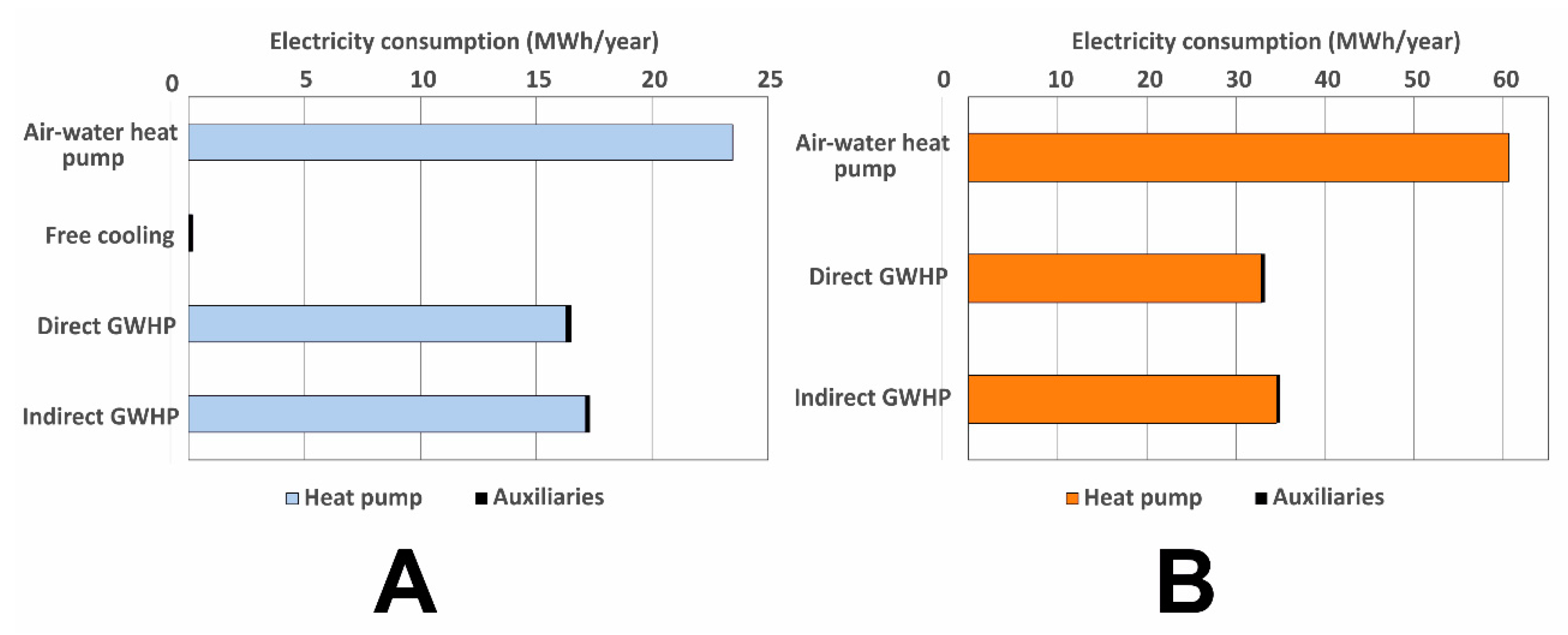
Results of the calculations reported in Figure A1A show that the free cooling option (n. 2) has a negligible electricity consumption (−99.1% compared to the air-source chiller) and the GWHP options (n. 3 and 4) provide appraisable energy savings of, respectively, 26.2% and 29.4% with and without the intermediate heat exchanger.
The direct heat exchange with groundwater cannot be performed for heating and, hence, option n. 2 cannot be considered. Three options are therefore available for heating:
- (5)
- Air-water chiller (Carrier 30 RQSY 100, see [50]) with a SCOP = 3.30 at typical radiant panel temperatures (30–35 °C);
- (6)
- (7)
- GWHP with intermediate heat exchanger (Figure 1C). The same reversible heat pump as case 3, but the efficiency is reduced to SEER = 5.79, a reduction of 0.3, which can be considered as a reasonable estimate for a condensation temperature increase of 5 °C due to the intermediate heat exchanger.
As show in Figure A1B, a noticeable reduction of energy consumption is achieved in heating mode, i.e., 41.6–48.8% with the two GWHP options (n. 6 and 7) compared to the air-source heat pump (n. 5).
Figure A1.
(A) Electricity consumption of different cooling options (free cooling, GWHP with direct heat exchange and GWHP with an intermediate heat exchanger), compared to the base case (air–water chiller). (B) Electricity consumption of different heating options (GWHP with direct heat exchange and GWHP with an intermediate heat exchanger) compared to an air-water heat pump.

Appendix B.2. Different Thermal Use Schemes in an Air Stripping Unit (ASU)
An air stripping unit can implement the pre-heating of water or air in order to foster the volatilization of VOCs dissolved in groundwater. Figure 3 shows three options for water preheating, namely:
- (A)
- heat discharge into contaminated water as a pre-heating before the air stripping treatment, thus avoiding (or reducing) further heat inputs to improve the stripping process;
- (B)
- heat recovery after the treatment, if water pre-heating is required for air stripping;
- (C)
- implementation of both the heat exchanges through a heat pump, i.e., extracting heat from the stripping column effluent (connected to the heat pump evaporator) to preheat groundwater before the air stripping with the heat delivered by the heat pump in the condensation phase.
Option A is a variant of the free-cooling option reported in Figure 1A. It is, by far, the least energy-intensive alternative, as the only energy consumption is the circulation of groundwater through a heat exchanger. A pressure drop through the heat exchanger results in a power consumption of 7.77 Watt per m3/h treated (see Equation (A1)).
Option B presents the advantage of providing a higher-temperature source for a heat pump exploiting the heat previously provided to water to volatilize VOCs. The benefit in terms of energy saving could be expressed as an increase of the heat pump COP. For example, the above-mentioned Carrier Aquasnap 30 WG 090 [50] has a COP = 3.56 for heating with a condenser entering/leaving water temperature of 47 °C/55 °C and an evaporator entering/leaving water temperature of 10 °C/7 °C. A COP = 4.16 (i.e., +0.6) with a 10 °C increase at the evaporator side (i.e., 20 °C/17 °C) results in a reduction of 14.4% of the electrical power absorbed by the heat pump, which is due to the choice of performing the heat exchange on water leaving the ASU unit instead of groundwater abstracted from the aquifer.
Option C allows one to provide the heat withdrawn from the outlet to water at the inlet of the air stripping unit, thus fostering the volatilization of VOCs. The thermal power in pre-heating mode is:
where is the temperature increase in pre-heating at the ASU inlet and is the temperature drop applied to water leaving the ASU.
From Equation (A3), it turns out that the temperature increase for pre-heating is equal to:
As the COP is expected to be very high due to the small temperature difference between evaporator and condenser temperature, Equation (A4) can be simplified to:
Using a heat pump for pre-heating at the ASU inlet results in a noticeable reduction of non-renewable primary energy consumed and of greenhouse gas emissions, compared to the use of a fossil-fuel boiler. Let us assume a heat pump and a non-renewable primary energy factor for the electrical energy, and let us compare it with a gas boiler with and .
The resulting non-renewable primary energy factors are equal to for the heat pump and . This means that using a heat pump to pre-heat water at the ASU inlet results in a 62.4% reduction of the fossil-fuel demand.
Regarding the GHG emissions, adopting the emission factors suggested in [49] for a gas boiler and for the Italian electrical grid, the use of the heat pump for pre-heating cuts greenhouse gas emissions by 78.5%.
Therefore, a heat pump recovering heat from the air stripping unit outlet can pre-heat the water with a much lower environmental impact.
Appendix C
Table A2.
Synopsis of Italian national interest contaminated sites (SIN).
| # | Site Name | Region | Area (ha) | Description | Notes |
|---|---|---|---|---|---|
| 1 | Porto Marghera (Venice) | Veneto | 1618 | Former and active petrochemical plants. | Groundwater drainage system (55 m3/h) installed with a treatment plant [56]. |
| 2 | Eastern Naples | Campania | 834 | Active and former industrial sites | Pumping + recharge wells to avoid saline intrusion [57]. |
| 3 | Gela | Sicily | 795 | Active petrochemical plants | Hydraulic barrier of 78 wells, with groundwater treatment plant, for a flow rate of 250 m3/h [58,59]. |
| 4 | Priolo | Sicily | 5814 | Active petrochemical plants | P&T active (600 m3/h) with sustainable reuse of treated waters [58,60]. |
| 5 | Manfredonia | Apulia | 216 | Former petrochemical plants and 3 landfills | P&T with reinjection wells on the boundary, low permeability aquifer, flow rate 120 m3/h [61]. |
| 6 | Brindisi | Apulia | 5851 | Chemical plants, coal power station | 5 P&T foreseen in the reclamation project for a total flow rate of 215 m3/h [62]. |
| 7 | Taranto | Apulia | 4383 | Steel and cement production, oil refining | Reclamation project still at early phases. Two P&T systems foreseen, with a total flow rate of 100 m3/h [63]. |
| 8 | Cengio and Saliceto | Liguria and Piedmont | 77 | Former chemical plant | P&T installed with a capacity of 600 m3/h [64]. |
| 9 | Piombino | Tuscany | 931 | Steel production plant | P&T with a flow rate of 11 m3/h [65]. |
| 10 | Massa and Carrara | Tuscany | 116 | Numerous industrial activities | P&T system with a flow rate of 160 m3/h [66]. |
| 11 | Casale Monferrato | Piedmont | 73,895 | Asbestos processing (Eternit) | Area contaminated by asbestos. No P&T foreseen. |
| 12 | Balangero | Piedmont | 314 | Former asbestos quarry | Area contaminated by asbestos. Quarry lake but no P&T foreseen. |
| 13 | Pieve Vergonte | Piedmont | 42 | Former chemical plant | P&T active (350–850 m3/day) with a foreseen expansion to 1250 m3/h [67,68]. |
| 14 | Sesto San Giovanni | Lombardy | 255 | Former steel processing plant | P&T active to remediate CAHs, flow rate 200 m3/h [69]. |
| 15 | Pioltello Rodano | Lombardy | 85 | Chemical and pharmaceutical industries | Groundwater remediation activities to be designed [70]. |
| 16 | Bagnoli (Naples) | Campania | 249 | Former steel and cement production plant, former asbestos processing plant | P&T foreseen, 270 m3/h [71]. |
| 17 | Tito | Basilicata | 315 | Former chemical plant | Hydraulic barrier with a capacity of 90 m3/h [72]. |
| 18 | Crotone, Cassano and Cerchiara | Calabria | 530 | Former metal working industries | P&T installed with a capacity of 88 m3/h [73]. |
| 19 | Fidenza | Emilia-Romagna | 25 | Former chemical industry | Hydraulic barrier with 3 wells. New settlement foreseen in the site [74]. |
| 20 | Torviscosa Caffaro | Friuli Venezia Giulia | 201 | Former chemical industry | Hydraulic barriers, flow rate of 47 m3/h [75]. |
| 21 | Trieste | Friuli Venezia Giulia | 506 | Steel production plant | Hydraulic barrier to be realized, with a capacity of 15 m3/h [76]. |
| 22 | Cogoleto Stoppani | Liguria | 45 | Chemical industry | 12 pumping wells (total flow rate 36 m3/h) for emergency dewatering [77]. |
| 23 | Fibronit Bari | Apulia | 15 | Asbestos processing | Asbestos contamination in groundwater [78] but no P&T implemented until now. |
| 24 | Sulcis, Iglesiente, Guspinese | Sardinia | 19,751 | Coal/bauxite mining areas and metal working/chemical industries | In Portovesme, 3 P&T systems, and another barrier of 61 wells is foreseen. Total flow rate: 514 m3/h [79]. |
| 25 | Biancavilla | Sicily | 330 | Asbestos-like mineral (fluoro-edenite) | No P&T foreseen. |
| 26 | Livorno | Tuscany | 206 | Oil refining | Hydraulic barrier with 42 wells [80]. |
| 27 | Terni Papigno | Umbria | 655 | Former and actual chemical, electric, textile, iron & steel industries | Heavy metals found in groundwater. A small P&T system was implemented in 2016 [54]. |
| 28 | Emarèse | Valle d’Aosta | 23 | Former asbestos minerals quarry | No P&T implemented or foreseen. |
| 29 | Northern Trento | Trento | 24 | PAH, aromatic solvents, phenols, Pb and Hg by former petrochemical industries | Hydraulic barrier and GW activated carbon treatment plant [81]. |
| 30 | Brescia Caffaro | Lombardy | 2109 | PCB, PAH, heavy metals | P&T systems in 2 sites (Oto Melara and Baratti) [75,82]. |
| 31 | Broni | Lombardy | 14 | Former asbestos cement industry | No P&T systems [83]. |
| 32 | Falconara Marittima | Marche | 105 | Former refinery and oil products storage. HC, PAH, heavy metals | Hydraulic barrier along coastline as urgent safety measure [84]. |
| 33 | Serravalle Scrivia | Piedmont | 74 | Former industry of oil, lubricants | Hydraulic containment foreseen by means of barrier wall. |
| 34 | Lakes of Mantua and chemical pole | Lombardy | 614 | PAH, organohalogen compounds, HC, heavy metals (esp. Hg) by former refineries, petrochemical industries | Hundreds of wells for hydraulic barrier [85]. |
| 35 | Orbetello (former SITOCO) | Tuscany | 204 | Former chemical industry released heavy metals, PCB, dioxin | 20 wells foreseen in 2009 for water table lowering, with a flow rate of 30 m3/h [86]. Hydraulic barrier for deep aquifer. |
| 36 | Porto Torres | Sardinia | 1874 | Petrochemical, chemical, engineering industry; storage tanks for oil products | P&T system (200 + 50 m3/h, see Ref. [56]) and other remediation techniques (MPE). Water disposal in the sea. |
| 37 | Basento valley | Basilicata | 3300 | Asbestos-like minerals and others | A P&T system foreseen with a flow rate of 90 m3/h [87]. |
| 38 | Milazzo | Sicily | 549 | Refineries and industrial district | P&T foreseen in one of the industrial site [54]. |
| 39 | Bussi | Abruzzo | 232 | Chlorinated solvents by former industrial sites and industrial landfills | P&T system active with a flow rate of 120 m3/h [88]. |
| 40 | Sacco river basin | Latium | ~7200 | Lindane and beta-esachlorocycloesane by former chemical industrial sites | Hydraulic barrier of 29 wells. |
| 41 | Train maintenance workshop of Bologna | Emilia-Romagna | n.a. | Asbestos-like minerals and others | Site characterization ongoing. |
References
- Department of Defence—Australian Government Guidelines for Consideration of Sustainability in Remediation of Contaminated sites. Available online: http://bit.ly/36SiObg (accessed on 20 February 2018).
- Suthersan, S.S.; Horst, J.; Schnobrich, M.; Welty, N.; McDonough, J. Remediation Engineering: Design Concepts; CRC Press: Boca Raton, FL, USA, 2016; ISBN 1-4987-7336-2. [Google Scholar]
- EPA, J. Pump-and-Treat Ground-Water Remediation: A Guide for Decision Makers and Practitioners; US Environmental Protection Agency: Washington, DC, USA, 1996. [Google Scholar]
- Fiedler, L.; Pachon, C. Recent Trends in the Selection of Remedies for Groundwater, Soil, and Sediment at Superfund Sites. Groundw. Monit. Remediat. 2018, 38, 13–18. [Google Scholar] [CrossRef]
- Podobnik, J.C.; Horst, B.I. A Survey of Sites Using Pump and Treat. Remediation Methods and a Survey Study of Applying Geothermal Heat Pump Systems to Pump and Treat. Sites at Lawrence Livermore National Laboratory; Lawrence Livermore National Laboratory: Livermore, CA, USA, 1998. [Google Scholar]
- Patyn, J.; Lookman, R. The Combination of Aquifer Thermal Energy Storage (ATES) and Groundwater Remediation; Terra Energy nv, VITO, OVAM, VMM, Utrecht city, VEA: Mechelen, Belgium, 2012; p. 38. [Google Scholar]
- Potter, T.M. Geothermal/Ground-Source Heat Pump Application Opportunities under the MCP 2015. Available online: http://bit.ly/2Mkir1v (accessed on 20 February 2018).
- Farr, G.; Sadasivam, S.; Watson, I.A.; Thomas, H.R.; Tucker, D. Low enthalpy heat recovery potential from coal mine discharges in the South Wales Coalfield. Int. J. Coal Geol. 2016, 164, 92–103. [Google Scholar] [CrossRef] [Green Version]
- Peralta Ramos, E.; Breede, K.; Falcone, G. Geothermal heat recovery from abandoned mines: A systematic review of projects implemented worldwide and a methodology for screening new projects. Environ. Earth Sci. 2015, 73, 6783–6795. [Google Scholar] [CrossRef]
- Bailey, M.T.; Gandy, C.J.; Watson, I.A.; Wyatt, L.M.; Jarvis, A.P. Heat recovery potential of mine water treatment systems in Great Britain. Int. J. Coal Geol. 2016, 164, 77–84. [Google Scholar] [CrossRef] [Green Version]
- Zajzon, N.; Žibret, G.; Aaltonen, J.; Rossi, C.; Bodo, B.; Silva, E.; Henley, S.; Mata, B.; Huxtable, P.; Fernandez, I.; et al. UNEXMIN: Underwater Explorer for Flooded Mines. Available online: www.unexmin.eu/ (accessed on 20 February 2018).
- Sarbu, I.; Sebarchievici, C. General review of ground-source heat pump systems for heating and cooling of buildings. Energy Build. 2014, 70, 441–454. [Google Scholar] [CrossRef]
- Casasso, A.; Sethi, R. Assessment and Minimization of Potential Environmental Impacts of Ground Source Heat Pump (GSHP) Systems. Water 2019, 11, 1573. [Google Scholar] [CrossRef] [Green Version]
- Menberg, K.; Bayer, P.; Zosseder, K.; Rumohr, S.; Blum, P. Subsurface urban heat islands in German cities. Sci. Total Environ. 2013, 442, 123–133. [Google Scholar] [CrossRef]
- Menberg, K.; Blum, P.; Kurylyk, B.L.; Bayer, P. Observed groundwater temperature response to recent climate change. Hydrol. Earth Syst. Sci. 2014, 18, 4453–4466. [Google Scholar] [CrossRef] [Green Version]
- Piga, B.; Casasso, A.; Pace, F.; Godio, A.; Sethi, R. Thermal Impact Assessment of Groundwater Heat Pumps (GWHPs): Rigorous vs. Simplified Models. Energies 2017, 10, 1385. [Google Scholar] [CrossRef] [Green Version]
- Pophillat, W.; Attard, G.; Bayer, P.; Hecht-Méndez, J.; Blum, P. Analytical solutions for predicting thermal plumes of groundwater heat pump systems. Renew. Energy 2018, 147, 2696–2707. [Google Scholar] [CrossRef]
- Banks, D. Thermogeological assessment of open-loop well-doublet schemes: A review and synthesis of analytical approaches. Hydrogeol. J. 2009, 17, 1149–1155. [Google Scholar] [CrossRef]
- Casasso, A.; Sethi, R. Modelling thermal recycling occurring in groundwater heat pumps (GWHPs). Renew. Energy 2015, 77, 86–93. [Google Scholar] [CrossRef] [Green Version]
- Rafferty, K. Scaling in Geothermal Heat Pump Systems. Available online: http://bit.ly/2NsmubK (accessed on 11 December 2018).
- Bezelgues-Courtade, S.; Martin, J.-C.; Schomburgk, S.; Monnot, P.; Nguyen, D.; Le Brun, M.; Desplan, A. Geothermal Potential of Shallow Aquifers: Decision-Aid Tool for Heat-Pump Installation. In Proceedings of the World Geothermal Congress, Bali Island, Indonesia, 25 April 2010. [Google Scholar]
- EPA Groundwater Pump and Treat Systems: Summary of Selected Cost and Performance Information at Superfund-Financed Sites. Available online: http://bit.ly/3922NkS (accessed on 12 December 2018).
- Marks, P.J.; Wujcik, W.J.; Loncar, A.F. Remediation Technologies Screening Matrix and Reference Guide, 2nd ed.; Roy F Weston Inc.: West Chester, PA, USA, 1994. [Google Scholar]
- Ahamad, K.U.; Jawed, M. Kinetics, equilibrium and breakthrough studies for Fe(II) removal by wooden charcoal: A low-cost adsorbent. Desalination 2010, 251, 137–145. [Google Scholar] [CrossRef]
- Chern, J.-M.; Wu, C.-Y. Desorption of dye from activated carbon beds: Effects of temperature, pH, and alcohol. Water Res. 2001, 35, 4159–4165. [Google Scholar] [CrossRef]
- Iovino, P.; Erto, A.; Capasso, S.; Natale, M.D.; Canzano, S.; Lama, A.; Musmarra, D. Experimental analysis of benzene derivative adsorption in single and binary systems using activated carbon. Int. J. Environ. Waste Manag. 2015, 16, 336–352. [Google Scholar] [CrossRef]
- Gupta, V.K.; Gupta, B.; Rastogi, A.; Agarwal, S.; Nayak, A. Pesticides removal from waste water by activated carbon prepared from waste rubber tire. Water Res. 2011, 45, 4047–4055. [Google Scholar] [CrossRef]
- Salman, J.M.; Njoku, V.O.; Hameed, B.H. Adsorption of pesticides from aqueous solution onto banana stalk activated carbon. Chem. Eng. J. 2011, 174, 41–48. [Google Scholar] [CrossRef]
- Dąbrowski, A.; Podkościelny, P.; Hubicki, Z.; Barczak, M. Adsorption of phenolic compounds by activated carbon—A critical review. Chemosphere 2005, 58, 1049–1070. [Google Scholar] [CrossRef]
- Bhattacharyya, K.G.; Gupta, S.S. Adsorption of a few heavy metals on natural and modified kaolinite and montmorillonite: A review. Adv. Colloid Interface Sci. 2008, 140, 114–131. [Google Scholar] [CrossRef]
- Xu, D.; Tan, X.L.; Chen, C.L.; Wang, X.K. Adsorption of Pb(II) from aqueous solution to MX-80 bentonite: Effect of pH, ionic strength, foreign ions and temperature. Appl. Clay Sci. 2008, 41, 37–46. [Google Scholar] [CrossRef]
- Senthil Kumar, P.; Ramalingam, S.; Senthamarai, C.; Niranjanaa, M.; Vijayalakshmi, P.; Sivanesan, S. Adsorption of dye from aqueous solution by cashew nut shell: Studies on equilibrium isotherm, kinetics and thermodynamics of interactions. Desalination 2010, 261, 52–60. [Google Scholar] [CrossRef]
- Kundu, S.; Gupta, A.K. Arsenic adsorption onto iron oxide-coated cement (IOCC): Regression analysis of equilibrium data with several isotherm models and their optimization. Chem. Eng. J. 2006, 122, 93–106. [Google Scholar] [CrossRef]
- Al-Degs, Y.S.; El-Barghouthi, M.I.; El-Sheikh, A.H.; Walker, G.M. Effect of solution pH, ionic strength, and temperature on adsorption behavior of reactive dyes on activated carbon. Dyes Pigments 2008, 77, 16–23. [Google Scholar] [CrossRef]
- Memon, G.Z.; Bhanger, M.I.; Akhtar, M.; Talpur, F.N.; Memon, J.R. Adsorption of methyl parathion pesticide from water using watermelon peels as a low cost adsorbent. Chem. Eng. J. 2008, 138, 616–621. [Google Scholar] [CrossRef]
- Ball, B.R.; Edwards, M.D. Air Stripping VOCs from Groundwater: Process Design Considerations. Environ. Prog. 1992, 11, 39–48. [Google Scholar] [CrossRef]
- Chuang, K.T.; Cheng, S.; Tong, S. Removal and Destruction of Benzene, Toluene, and Xylene from Wastewater by Air Stripping and Catalytic Oxidation. Ind. Eng. Chem. Res. 1992, 31, 2466–2472. [Google Scholar] [CrossRef]
- Ashworth, R.A.; Howe, G.B.; Mullins, M.E.; Rogers, T.N. Air-water partitioning coefficients of organics in dilute aqueous solutions. J. Hazard. Mater. 1988, 18, 25–36. [Google Scholar] [CrossRef]
- Staudinger, J.; Roberts, P.V. A critical compilation of Henry’s law constant temperature dependence relations for organic compounds in dilute aqueous solutions. Chemosphere 2001, 44, 561–576. [Google Scholar] [CrossRef]
- EPA Cost-Effective Design of Pump and Treat Systems. Available online: https://clu-in.org/download/remed/hyopt/factsheets/cost-effective_design.pdf (accessed on 17 September 2019).
- Langwaldt, J.H.; Puhakka, J.A. On-site biological remediation of contaminated groundwater: A review. Environ. Pollut. 2000, 107, 187–197. [Google Scholar] [CrossRef]
- Beretta, G.P. Some aspects of the state of the art of contaminated sites remediation in Italy. Acque Sotter. Ital. J. Groundw. 2015, 4, 27–40. [Google Scholar] [CrossRef] [Green Version]
- ISPRA, S.I.N. Siti di Interesse Nazionale—Stato delle procedure per la bonifica. Dicembre 2018. Available online: http://bit.ly/2MjNp9P (accessed on 10 April 2019).
- Majone, M.; Rolle, E.; Petrangeli Papini, M.; Beretta, G.; Cicconi, V.; Maffucci, M. Messa in sicurezza e bonifica di falde contaminate: un’analisi delle tecnologie impiegate a partire dall’applicazione del d.m. 471/99. La chimica e l’industria 2009, 1, 104–109. [Google Scholar]
- Beretta, G.P.; Coppola, G.; Pona, L.D. Solute and heat transport in groundwater similarity: Model application of a high capacity open-loop heat pump. Geothermics 2014, 51, 63–70. [Google Scholar] [CrossRef]
- Papakostas, K.T.; Michopoulos, A.K.; Kyriakis, N.A. Equivalent full-load hours for estimating heating and cooling energy requirements in buildings: Greece case study. Appl. Energy 2009, 86, 757–761. [Google Scholar] [CrossRef]
- Rienecker, M.M.; Suarez, M.J.; Gelaro, R.; Todling, R.; Bacmeister, J.; Liu, E.; Bosilovich, M.G.; Schubert, S.D.; Takacs, L.; Kim, G.-K.; et al. MERRA: NASA’s modern-era retrospective analysis for research and applications. J. Clim. 2011, 24, 3624–3648. [Google Scholar] [CrossRef]
- Pfenninger, S.; Staffell, I. Renewables.ninja. Available online: https://www.renewables.ninja/ (accessed on 5 December 2019).
- Casasso, A.; Capodaglio, P.; Simonetto, F.; Sethi, R. Environmental and Economic Benefits from the Phase-out of Residential Oil Heating: A Study from the Aosta Valley Region (Italy). Sustainability 2019, 11, 3633. [Google Scholar] [CrossRef] [Green Version]
- Carrier Heating, Ventilation and Air Cooling. Catalogue 2018/2019. Available online: http://bit.ly/2R3bZ27 (accessed on 29 November 2019).
- Lo Russo, S.; Civita, M. Hydrogeological and thermal characterization of shallow aquifers in the plain sector of Piemonte region (NW Italy): Implications for groundwater heat pumps diffusion. Environ. Earth Sci. 2010, 60, 703–713. [Google Scholar] [CrossRef]
- Provincia Autonoma di Trento Map of Groundwater Temperatures in the Province of Trento. Available online: http://bit.ly/35yqO12 (accessed on 18 December 2019).
- A2A A2A District Heating Network of Brescia. Available online: http://bit.ly/323ShF7 (accessed on 21 September 2019).
- Braga, C.; Zaratti, F. Commissione Parlamentare di Inchiesta Sulle Attività Illecite Connesse al ciclo dei Rifiuti e su Illeciti Ambientali ad esse Correlati. Relazione Sulle Bonifiche nei siti di Interesse Nazionale. Relatori: On. Chiara Braga e On. Filiberto Zaratti. Available online: http://bit.ly/2qasaz8 (accessed on 29 August 2018).
- Rivoire, M.; Casasso, A.; Piga, B.; Sethi, R. Assessment of Energetic, Economic and Environmental Performance of Ground-Coupled Heat Pumps. Energies 2018, 11, 1941. [Google Scholar] [CrossRef] [Green Version]
- SIMAM Groundwater Treatment Plants. Available online: http://bit.ly/2pmd4ql (accessed on 1 September 2019).
- SOGESID Napoli Orientale—Relazione di calcolo dell’impianto TAF. Available online: http://bit.ly/2pximPK (accessed on 15 January 2019).
- Farina, M.; Bifulco, S. Aggiornamenti sullo stato dell’arte dei Procedimenti di Bonifica nei siti SIN di Gela e Priolo (Update on the remediation of National Interest Sites of Gela and Priolo). Available online: http://bit.ly/36ZI9QQ (accessed on 1 September 2019).
- Italian Ministry of Environment SIN “Gela”. Resoconto Tavolo Tecnico del 1 Giugno 2017. Available online: http://bit.ly/2NB1gZa (accessed on 2 March 2018).
- ENI Syndial: Inaugurazione impianto TAF di Priolo. Available online: http://bit.ly/2tBYD2V (accessed on 2 March 2018).
- ARPA Puglia; Fascia, Antonio; Lacarbonara, Mina Focus Siti di Interesse Nazionale. SIN Manfredonia. Available online: http://bit.ly/2q9kUng (accessed on 11 February 2018).
- ARPA Puglia; Siti Contaminati. Available online: http://bit.ly/339TdsP (accessed on 8 February 2018).
- Taranto Port Authority I° Lotto degli Interventi di Messa in Sicurezza e Bonifica della falda in area ex Yard Belleli, Funzionale alla Realizzazione della Cassa di Colmata c.d. “ampliamento V Sporgente”. Available online: http://bit.ly/323aWRD (accessed on 12 January 2019).
- Ambiente Liguria ACNA. Available online: http://bit.ly/33aptMK (accessed on 9 February 2018).
- Italian Ministry of Environment Conferenza dei Servizi Ministeriale del 30 novembre 2012 relativa alla “Progettazione Preliminare del sistema di marginamento della colmata Nord, comprensivo della realizzazione e gestione del sistema di captazione della falda e progettazione preliminare dell’impianto di trattamento e riutilizzo delle acque di falda inquinate derivante dal sistema di marginamento pubblico previsto all’interno del SIN di Piombino” elaborato dalla Sogesid. Available online: http://bit.ly/2NwqGar (accessed on 12 February 2018).
- ENI Rewind ENI Rewind—Activities in the Site of Carrara Avenza. Available online: http://bit.ly/2WAk1Aj (accessed on 1 February 2019).
- Region Piemonte Deliberazione della Giunta Regionale 23 aprile 2013, n. 28-5712. Procedura di Valutazione ex art 12 della L.R. 40/98 con Contestuale Valutazione d’Incidenza per il Progetto Definitivo “Progetto Operativo di Bonifica del sito di Pieve Vergonte (VB)” Presentato da SYNDIAL. Available online: http://bit.ly/2qgMXAU (accessed on 28 February 2018).
- Troni, M. Presentazione casi specifici di Pieve Vergonte e Mantova. Available online: http://bit.ly/2Nqpg0Y (accessed on 16 January 2019).
- ARPA Lombardia; Sito di Interesse Nazionale di Sesto San Giovanni (MI). Relazione sullo stato di Contaminazione delle acque Sotterranee. Campagna Semestrale di Monitoraggio—Settembre 2017. Available online: http://bit.ly/2QdEzLU (accessed on 13 February 2018).
- Regione Lombardia, Sito di Interesse Nazionale di Pioltello e Rodano. Available online: http://bit.ly/2JH7Tbw (accessed on 13 February 2018).
- Invitalia; Programma di risanamento ambientale e di rigenerazione urbana. Sito di Rilevante Interesse Nazionale di Bagnoli-Coroglio. Available online: http://bit.ly/2Sg7jGt (accessed on 14 February 2018).
- D’Aprile, L. SIN Tito—Verbale della Conferenza dei Servizi istruttoria del 12.02.2015. Available online: http://bit.ly/2ShpOuu (accessed on 14 February 2018).
- ENI Rewind ENI Rewind—Activities in the Site of Crotone. Available online: http://bit.ly/3274Qj5 (accessed on 1 February 2019).
- Savigni, G.; Pratissoli, A.; Drufuca, A.; Battaiotto, S.; Denti, R.; Teneggi, S.; Ugolini, C.; Spallanzani, N.; Ganapini, S.; Magnani, G.; et al. VIA sito di Interesse Nazionale di Fidenza. Sintesi Non Tecnica. Available online: http://bit.ly/2WBleqJ (accessed on 12 October 2019).
- Bratti, A.; Compagnone, G.; Cominelli, M. Commissione Parlamentare di Inchiesta sulle attività Illecite Connesse al ciclo dei rifiuti e su Illeciti Ambientali ad esse correlati. Relazione sui siti contaminati gestiti dalla società Caffaro a Torviscosa, Brescia, Colleferro e Galliera. Available online: http://bit.ly/2C7mXKY (accessed on 9 February 2018).
- Invitalia; Accordo di Programma “Disciplina degli Interventi Relativi alla Riqualificazione delle Attività Industriali e Portuali e del Recupero Ambientale nell’area di crisi Industriale Complessa di Trieste”. Available online: http://bit.ly/2ZbJeSE (accessed on 15 February 2018).
- Ambiente Liguria, Stoppani. Available online: http://bit.ly/2Zf5R8I (accessed on 9 February 2018).
- Fracassi, F.; Laricchiuta, S. Bonifica del sito Inquinato Fibronit Bari. Relazione di Consulenza Tecnica per la Procura della Repubblica di Bari. Available online: http://bit.ly/2Wz0KPu (accessed on 2 March 2018).
- Regione Sardegna Focus sulle bonifiche dei suoli e della falda nell’area industriale di Portovesme: I programmi a integrale carico delle aziende. Attuazione al 31 maggio 2017. Available online: http://bit.ly/36p9axj (accessed on 28 February 2018).
- ARPA Toscana Il sito di bonifica di interesse nazionale di Livorno. Available online: http://bit.ly/36Z6Qww (accessed on 2 March 2018).
- Italian Ministry of Environment Sito d’Interesse Nazionale “Trento Nord”. Verbale della conferenza di Servizi decisoria tenutasi presso il Ministero dell’Ambiente e della Tutela del Territorio in data 22 novembre 2005 ai sensi dell’art. 14 L. n. 241/90 e sue successive modifiche ed integrazioni. Available online: http://bit.ly/36rvG95 (accessed on 15 February 2018).
- Official Site of the Commissioner of the Contaminated Site of Brescia—Caffaro. Available online: http://bresciacaffaro.it/ (accessed on 2 March 2018).
- Regione Lombardia Report on the Contaminated Site of Broni. Available online: http://bit.ly/2JWfRh5 (accessed on 3 March 2018).
- Italian Ministry of Environment; Region Marche; Province of Ancona; Municipality of Falconara Marittima; Port authority of Ancona Accordo di programma per la definizione degli interventi di messa in sicurezza e bonifica delle aree comprese nel Sito di Interesse Nazionale di Falconara. Available online: http://bit.ly/338wldo (accessed on 26 February 2018).
- Italian Ministry of Environment—Accordo di Programma per la Definizione degli Interventi di Messa in Sicurezza D’emergenza e Successiva Bonifica nel Sito di Interesse Nazionale di “Laghi di Mantova e Polo Chimico”. Available online: http://bit.ly/2C2oBh5 (accessed on 2 March 2018).
- Italian Ministry of Environment Sito di Interesse Nazionale “Orbetello Area ex SITOCO”. Verbale della Conferenza di Servizi Istruttoria del 29.05.2013. Available online: http://bit.ly/2NaFUTL (accessed on 1 March 2018).
- D’ Aprile, L.; Rolli, A.P.; Gravino, S. Siti D’interesse Nazionale di “Area Industriale di Tito Scalo” e “Area Industriale della Val Basento”. Verbale della Conferenza di Servizi Decisoria Convocata presso il MATTM in data 16.05.2016, ai sensi dell’art. 14 comma 2 della Legge n. 241/90 e Successive Integrazioni e Modifiche. Available online: http://bit.ly/338dpeR (accessed on 29 August 2018).
- Zueblin Umwelttechnik Züblin Umwelttechnik GmbH—Impianto T.A.F. per trattamento acque di falda contaminate da CHC e mercurio, Bussi sul Tirino. Available online: http://bit.ly/2C2o6nf (accessed on 11 January 2019).
Figure 1.
Possible heat uses for P&T systems: (A) direct heat exchange for cooling; (B) heat pump directly connected to the well loop; (C) heat pump connected to the well loop through an intermediate heat exchanger.
Figure 1.
Possible heat uses for P&T systems: (A) direct heat exchange for cooling; (B) heat pump directly connected to the well loop; (C) heat pump connected to the well loop through an intermediate heat exchanger.

Figure 2.
Possible positions for heat exchange: (A) upstream of all treatment stages; (B) downstream of all treatment stages; (C) between two treatment stages.
Figure 2.
Possible positions for heat exchange: (A) upstream of all treatment stages; (B) downstream of all treatment stages; (C) between two treatment stages.

Figure 3.
Possible positions for heat exchange in an air stripping system with an air stripping unit (ASU): (A) heat discharge from a (free) cooling system on groundwater before treatment; (B) downstream heat recovery downstream of the treatment; (C) heat recovery downstream of the treatment with a heat pump used to preheat water before treatment.

Figure 4.
Map of the 41 “Siti di Interesse Nazionale (SIN)” (contaminated Sites of National Interest). For numbering, refer to Appendix C.
Figure 4.
Map of the 41 “Siti di Interesse Nazionale (SIN)” (contaminated Sites of National Interest). For numbering, refer to Appendix C.

Table 1.
Flow rate treated in 23 Italian contaminated sites of national interest (SIN) and thermal power that could be exchanged with P&T systems.
Table 1.
Flow rate treated in 23 Italian contaminated sites of national interest (SIN) and thermal power that could be exchanged with P&T systems.
| No. | Site | Flow Rate (m3/h) | Thermal Power, ΔT = 4 K (kW) | FLEH Heating (h/a) | FLEH Cooling (h/a) | Avoided GHG (Ton CO2 eq/a) |
|---|---|---|---|---|---|---|
| 30 | Brescia Caffaro | 1400 | 6496 | 2151 | 728 | 3001 |
| 13 | Pieve Vergonte | 1250 | 5800 | 2589 | 268 | 3224 |
| 4 | Priolo | 600 | 2784 | 1423 | 1011 | 851 |
| 8 | Cengio e Saliceto | 600 | 2784 | 2151 | 608 | 1286 |
| 24 | Sulcis-Iglesiente-Guspinese | 514 | 2385 | 1424 | 921 | 729 |
| 32 | Falconara Marittima | 400 | 1856 | 1558 | 934 | 621 |
| 16 | Bagnoli | 270 | 1253 | 1394 | 968 | 375 |
| 2 | Napoli Orientale | 258 | 1197 | 1394 | 968 | 358 |
| 3 | Gela | 250 | 1160 | 1439 | 993 | 359 |
| 36 | Porto Torres | 250 | 1160 | 1470 | 920 | 366 |
| 6 | Brindisi | 215 | 998 | 1193 | 1208 | 256 |
| 14 | Sesto San Giovanni | 200 | 928 | 2202 | 751 | 439 |
| 10 | Massa e Carrara | 160 | 743 | 1752 | 634 | 280 |
| 5 | Manfredonia | 120 | 557 | 1419 | 1051 | 170 |
| 39 | Bussi sul Tirino | 120 | 557 | 2336 | 476 | 279 |
| 7 | Taranto | 100 | 464 | 1416 | 1050 | 141 |
| 17 | Tito | 90 | 418 | 2070 | 601 | 186 |
| 18 | Crotone | 88 | 408 | 1483 | 1109 | 130 |
| 1 | Marghera | 55 | 255 | 1958 | 909 | 107 |
| 20 | Torviscosa Caffaro | 47 | 218 | 1947 | 659 | 91 |
| 22 | Cogoleto Stoppani | 36 | 167 | 1912 | 642 | 69 |
| 29 | Trento Nord | 17 | 79 | 2784 | 138 | 47 |
| 9 | Piombino | 11 | 51 | 1253 | 962 | 14 |
| TOTAL | 7051 | 32,718 | na | na | 13,378 |
© 2019 by the authors. Licensee MDPI, Basel, Switzerland. This article is an open access article distributed under the terms and conditions of the Creative Commons Attribution (CC BY) license (http://creativecommons.org/licenses/by/4.0/).
Share and Cite
MDPI and ACS Style
Casasso, A.; Tosco, T.; Bianco, C.; Bucci, A.; Sethi, R. How Can We Make Pump and Treat Systems More Energetically Sustainable? Water 2020, 12, 67. https://doi.org/10.3390/w12010067
AMA Style
Casasso A, Tosco T, Bianco C, Bucci A, Sethi R. How Can We Make Pump and Treat Systems More Energetically Sustainable? Water. 2020; 12(1):67. https://doi.org/10.3390/w12010067
Chicago/Turabian StyleCasasso, Alessandro, Tiziana Tosco, Carlo Bianco, Arianna Bucci, and Rajandrea Sethi. 2020. "How Can We Make Pump and Treat Systems More Energetically Sustainable?" Water 12, no. 1: 67. https://doi.org/10.3390/w12010067
Note that from the first issue of 2016, this journal uses article numbers instead of page numbers. See further details here.