Exploring Proper Spacing Threshold of Non-Submerged Spur Dikes with Ipsilateral Layout


1
Department of Hydraulic Engineering, Colledge of Civil Engineering and Architecture, Zhejiang University, Hangzhou 310058, China
2
Teaching Center, Zhejiang Open University, Hangzhou 310012, China
3
Department of Architecture and Civil Engineering, City University of Hong Kong, Hong Kong, China
*
Author to whom correspondence should be addressed.
Water 2020, 12(1), 172; https://doi.org/10.3390/w12010172
Submission received: 25 November 2019
/
Revised: 17 December 2019
/
Accepted: 30 December 2019
/
Published: 7 January 2020
(This article belongs to the Special Issue Management of Urban Water Services)
Abstract
:Concerning the clustering of spur dikes on river systems, the spacing thresholds of twin spur dikes are important parameters to influence the estimations on the impact scales of spur dike groups and the overall responses of river systems. In this study, both numerical investigations and experimental measurements are proceeded to quantify the influence of the spacing threshold of non-submerged twin spur dikes with ipsilateral and orthogonal layout in a straight rectangular channel. Through dimensional analysis, three normalized indices, i.e., Froude number Fr, ratios of channel width to dike length B/b, and ratios of channel width to water depth B/h are identified as the main influencing factors of the relative spacing threshold Sc/b, i.e., dike spacing threshold to dike length. The simulation results indicate that the similarity of mean velocity along the water depth nearby the tips of twin spur dikes is determined by the criterion of the spacing threshold of non-submerged twin spur dikes with ipsilateral and orthogonal layout in straight rectangular channel. The results also show that: Fr plays the least impact among the three influencing factors; with the fixed values of Fr and B/h, the relative threshold Sc/b sharply increases first and then decreases slightly as B/b factor increases, with which the relationship presents approximately convex quadratic function; while both Fr and B/b are fixing, the Sc/b changes oppositely, i.e., slightly increasing first and then sharply decreasing as B/h increases, which, again presents a convex quadratic function. Hence, the normalized empirical formula of spacing threshold can be deduced by multivariate regressions and verified by the corresponding measurements in good agreements. Such empirical formula further suggests that the reasonable spacing threshold ranges from 24b to 130b, which is wider than the recovery area scales found in literature. The outputs of this study provide foundation for the characterization of impact scales of spur dike groups.
1. Introduction
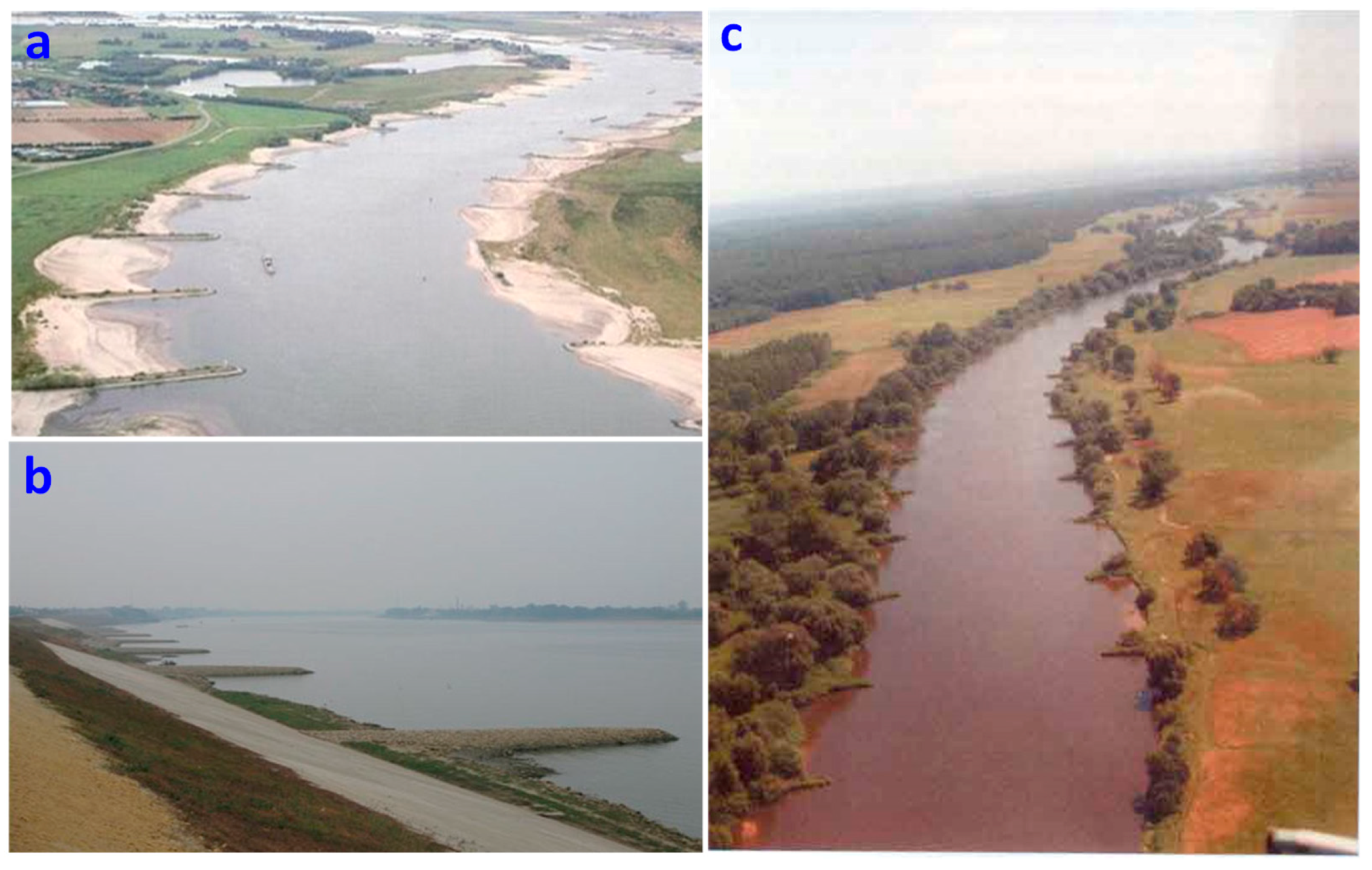
Rivers relate to human being’s living and development significantly and, are depicted as the cradle of human civilization. In order to exploit and train rivers to meet the requirements of human development efficiently, many river developments are built such as banks, dikes, dams, sluices, weirs and bridges, etc. [1,2]. These works help people to obtain benefits on one hand and, meanwhile may change and harm the original water-sediment process on the other hand [1,3,4]. In fact, the health of the river system may be affected or damaged due to the limited recognition of human-being and the unscientific development program of river works [5,6]. As one of the river works, spur dikes (shown in Figure 1) are widely used in river engineering such as channel regulation, flood prevention, river diversion and beach reclamation for maintaining the desired water depth, changing the direction of main flow, protecting river bank and bed, and acquiring land resource [7,8,9,10,11,12]. In spite of different types [8,13], the spur dikes present simple structure and multiple functions, which can be regarded as the simplification of many river works [12,14]. Hence, it is necessary and important to investigate spur dike hydraulics in details. After construction of spur dikes, the original channel becomes narrower and leads to changes in the moving characteristics of the flow current near spur dikes. In practice, spur dike exerts influences on river system usually in the form of groups as shown in Figure 1. These spur dikes (or groups) interact in a specific range, and such interaction gradually weakens beyond the critical range [2,8,15,16,17]. According to the degree of interaction, the spur dike groups on river system are classified into large-scale and small-scale [2,17]. The spur dike group in large-scale consists of sole spur dikes or small-scale spur dike groups, which are independent of each other without interaction; while spur dike group in small-scale consists of sole spur dikes, which interact with each other noticeably and present the role as a whole. To date, previous researches on spur dike hydraulics are mainly focusing on two aspects: (a) sole spur dike, including flow field around the spur dike [18,19,20,21], local scour mechanism [9,10], backwater effects [16,22], flow resistance and local head loss [16,23] and (b) spur dike group in small-scale, specifically including determination of reasonable spacing [24,25], estimations of water surface oscillation and water surface curves under different spacing [7]. These studies on spur dikes mainly concern the local response of river system. However, few studies have addressed the integrated, overall impact of spur dike group in large-scale on river system, though the cumulative effect of river works has been spotted both in engineering and academic domain [1,4,26]. Therefore, it is necessary to explore how a spur dike group in small-scale, in spite of its existing benign effect on local river training, would affect the whole river system as part of spur dike group in large-scale.
As mentioned above, clustering spur dikes in the river system presents the basis for investigating the cumulative effects and the comprehensive responses of river systems after construction of spur dikes. Since twin-spur-dike is the simplest spur dike group and the fundamental model regardless large- or small-scale spur dike groups, one can realize the clustering of spur dikes through establishing the calculation theory of the spacing threshold of twin spur dikes [2,17]. In this study, according to the flume experimental data, we use CFD (computational fluid dynamics) method [11,14,19,20,27] to quantitatively analyze the spacing threshold of non-submerged twin spur dikes with ipsilateral and orthogonal layout in straight rectangular channel. Unlike previous researches on reasonable spacing, which aimed to improve the training effects of small-scale spur dike group on the local segment of river system [8,24,25], this study aims to open the door for investigating the hydraulics of spur dike group in large-scale. In view of differences and similarities between the former researches and this study, we generally designate the spacing issue of spur dikes as “impact scale of spur dikes”.
2. Materials and Methods
2.1. Analyzing Models
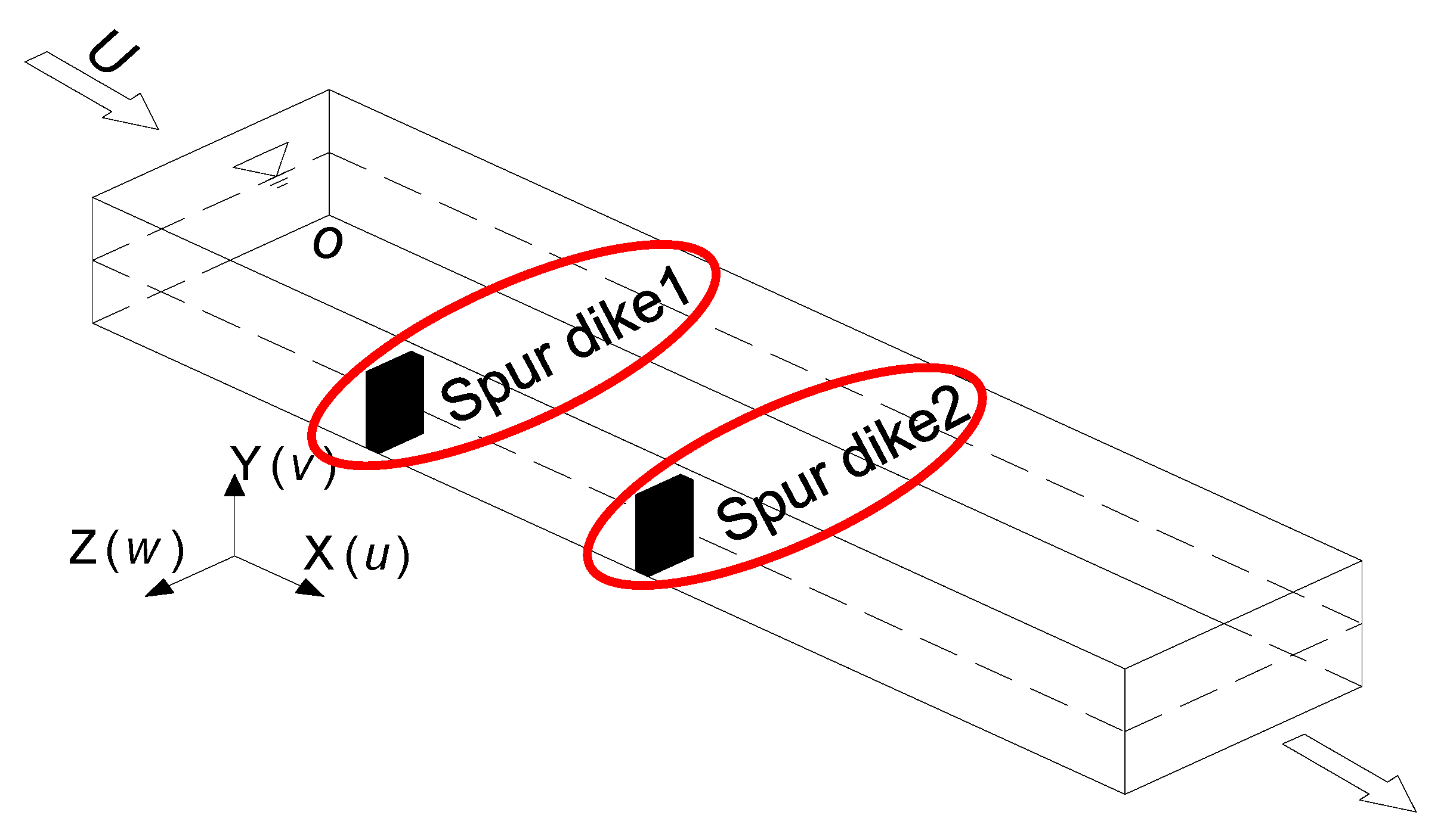
In this study, the flow problem of non-submerged twin spur dikes is generalized in Figure 2. Two identical spur dikes are perpendicular to the shoreline and in ipsilateral layout on the horizontal bed. The mean velocity of approaching flow is U. Under the Cartesian coordinate system, the direction along the main flow is X-axis, along the water depth Y-axis and parallel to the spur dike length Z-axis. The original coordinate is set at the point O, the bottom of flume as shown in Figure 2.
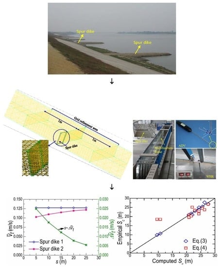
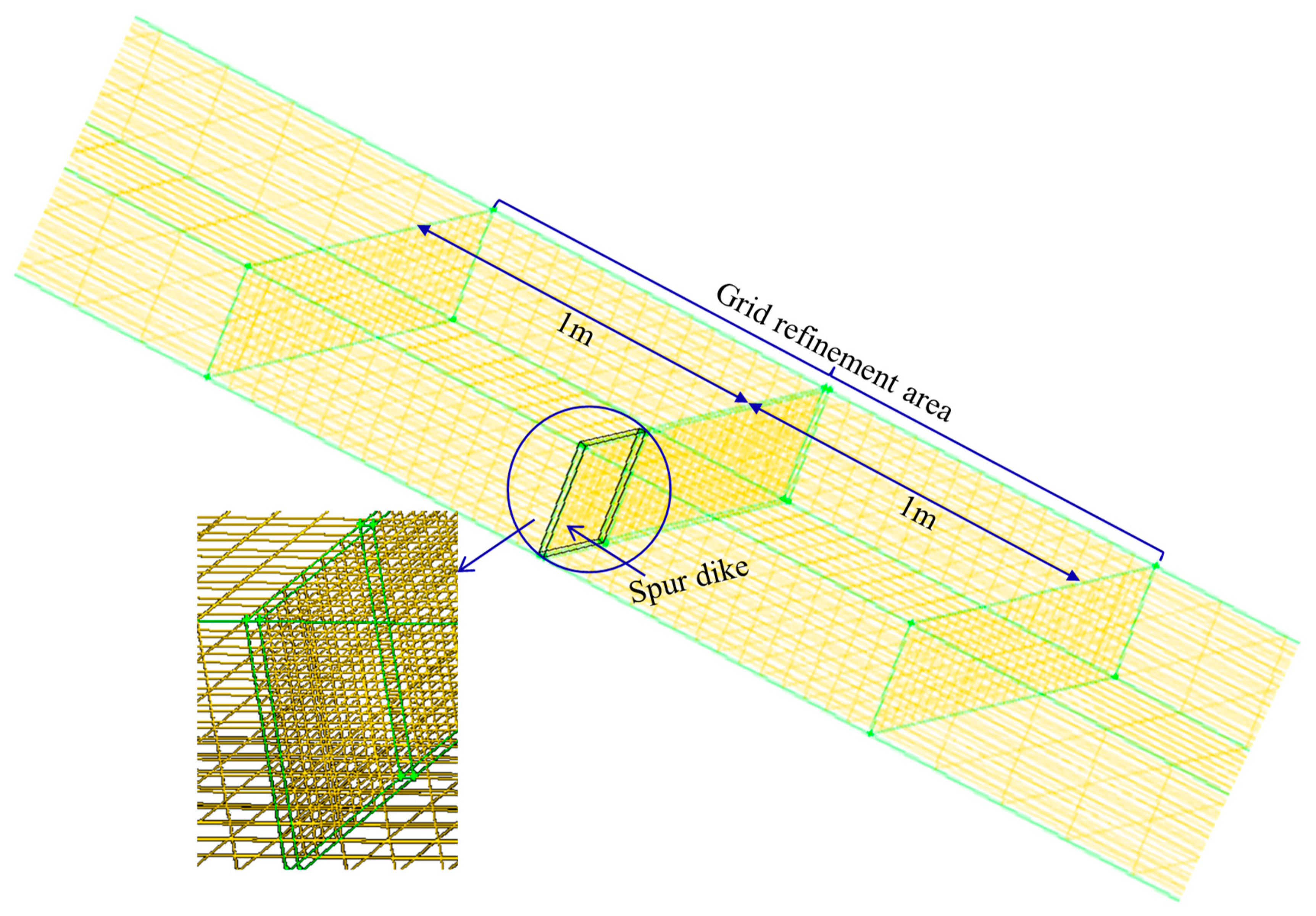
Spur dike flow is regarded as fully turbulent [22], and can be simulated through model [9,19,20]. In the current study, a commercial CFD software package, FLUENT, is used to build the numerical model of the flow around non-submerged twin spur dikes shown in Figure 2. The “pressure based” solver and the standard model in FLUENT are selected. The turbulence parameters of hydraulic diameter DH and the turbulence intensity I are calculated according to [28,29]. The SIMPLEC (semi-implicit method for pressure-linked equations consistent) algorithm is used to model the pressure-velocity coupling; the “body force weighted” method is applied for pressure discretization; and the discrete format of momentum, turbulent kinetic energy and turbulent dissipation rate are all assumed “first order upwind” scheme to guarantee the converged results. The approaching flow at the inlet uses “mass-flow-inlet”. Since the water surface slope of non-submerged spur dike flow hardly changes in flat-bottomed flume tests, the rigid lid assumption is used to model the free surface [15], i.e., assuming the constant free surface. The top surface of water body uses the “symmetry” as its boundary condition, whose tangential velocity may be not zero compared to the “wall”. The flow at the outlet is assumed as free outflow. The dike bodies and other faces of the flume are regarded as solid walls and meet the no-slip condition, and the “standard wall functions” are used to solve the steep variations of k and ε near the wall. The simulation domain is divided into several regular blocks for generating meshes by adding some appropriate auxiliary surfaces. The grids are hexahedral and refined in the vicinity of two spur dikes, as shown in Figure 3.
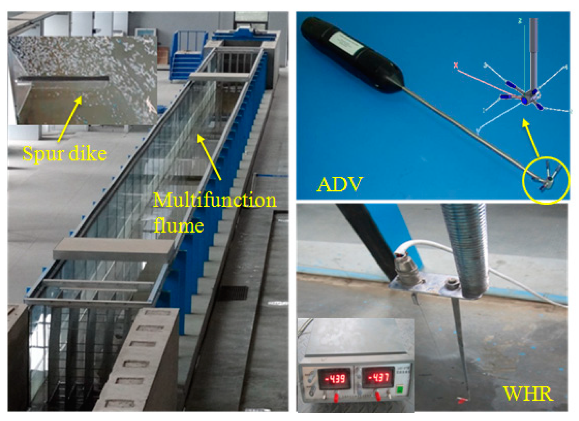
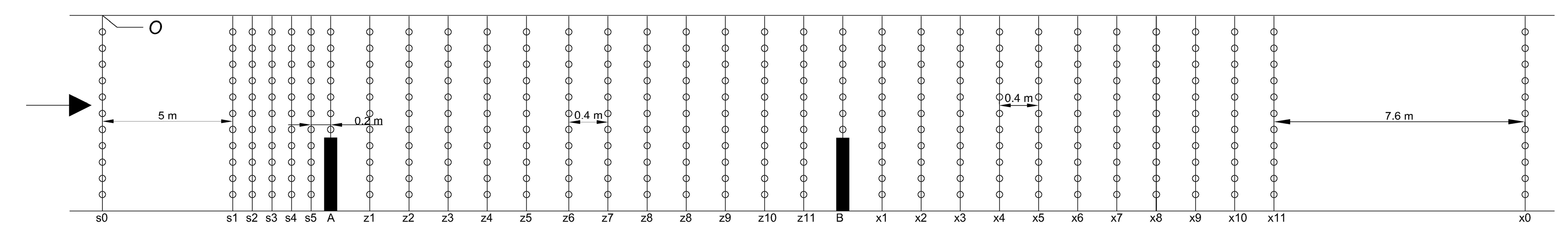
In order to verify the accuracy of the numerical model, three sets of flume experiments were conducted to obtain verification data. As shown in Figure 4, the experiments were carried out in the multifunction flume, which was 50 m long, 1.2 m wide and 1.4 m high and located at Jiangong Hall of Zhejiang University, China. The spur dikes were made of plexiglass and 1.6 cm thick and 40 cm high. Acoustic Doppler velocimeters (ADV) are used to measure velocities, and wave height recorders (WHR) to measure surface elevations. The distribution of measured cross-sections and points are shown in Figure 5. Spur dike 1 is arranged at cross-section A; spur dike 2 at cross-section B and initial Section s0 is set as the inlet. There are five cross-sections (i.e., s1–s5) at the upstream of spur dike 1 with equal interval of 0.2 m, eleven cross-sections (i.e., z1–z11) between two dikes with equal interval of 0.4 m, and also eleven cross-sections (i.e., x1–x11) at the downstream of spur dike 2 with equal interval of 0.4 m. The outlet cross-section x0 was 7.6 m from cross-section x11. The total numbers of measured cross-sections and points were 31 and 341 respectively. The coordinate origin was arranged at the bottom of flume at the point O in Figure 5.
2.2. Dimensional Analysis
Regarding the full turbulent flow such as spur dike flow, the molecular viscous effects can be neglected (i.e., Reynolds number) [22]. Further, the dike thickness of 0.016 m is less important and can be ignored compared with the dike spacing. Therefore, the following function is suggested by dimensional analysis for the spacing threshold Sc of non-submerged twin spur dikes with orthogonal layout in straight rectangular channel as:
where b represents the dike length, B the channel width, Q the flow rate of approaching flow, h the water depth, ρ the density of water and g the acceleration of gravity. According to Buckingham’s π-theorem [30], ρ, g and h are selected as the basic variables. The dimensionless equations are further deduced in Equation (2) listed below:
where Sc/b represents the relative spacing threshold, Fr the Froude number, B/h the section width-depth ratio and B/b the relative dike length.
2.3. Verification and Simulation Conditions
The verification conditions are listed in Table 1, where s is the dike spacing. The simulation cases are summarized in Table 2. Here, all cases, regarding the issue of “impact scale of spur dikes”, belong to subcritical flow with Fr < 1. The numerical simulations aim to investigate the relationships between Sc/b and Fr, B/b, B/h respectively and to build the empirical formula for spacing threshold Sc. Cases 1–5 correspond to different incoming flow rates or Fr, Cases 6–9 represent conditions of different dike lengths or B/b and Cases 10–13 reflect the situations under different B/h with Case 2 as communal one. To minimize the impact of incoming flow fluctuation and guarantee the sufficient developing range, the length scale of numerical flume is selected at 100 m with spur dike 1 fixed at X = 26 m and spur dike 2 movable along the flume bed.
3. Results and Discussions
3.1. Verification of Numerical Model
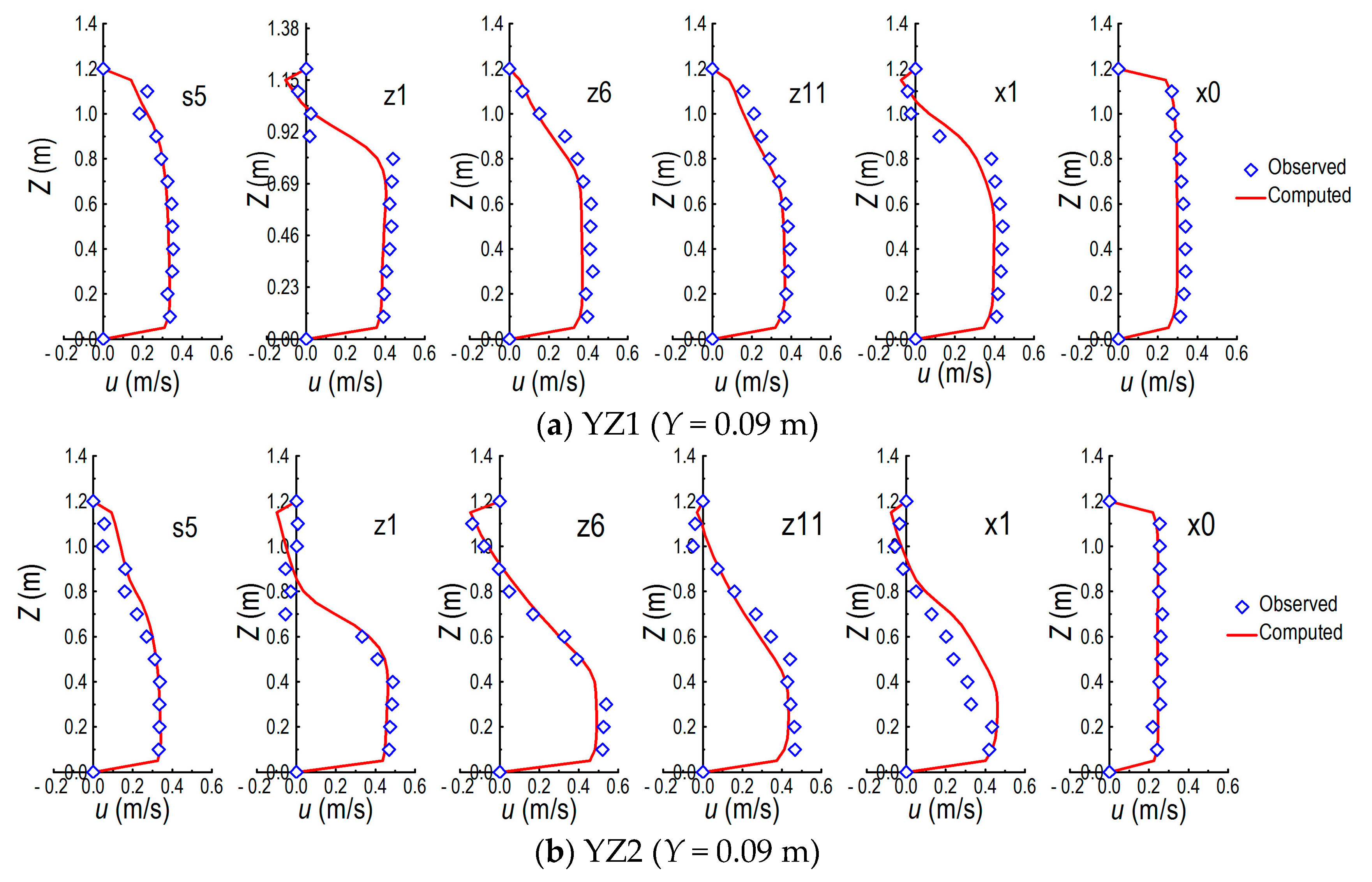
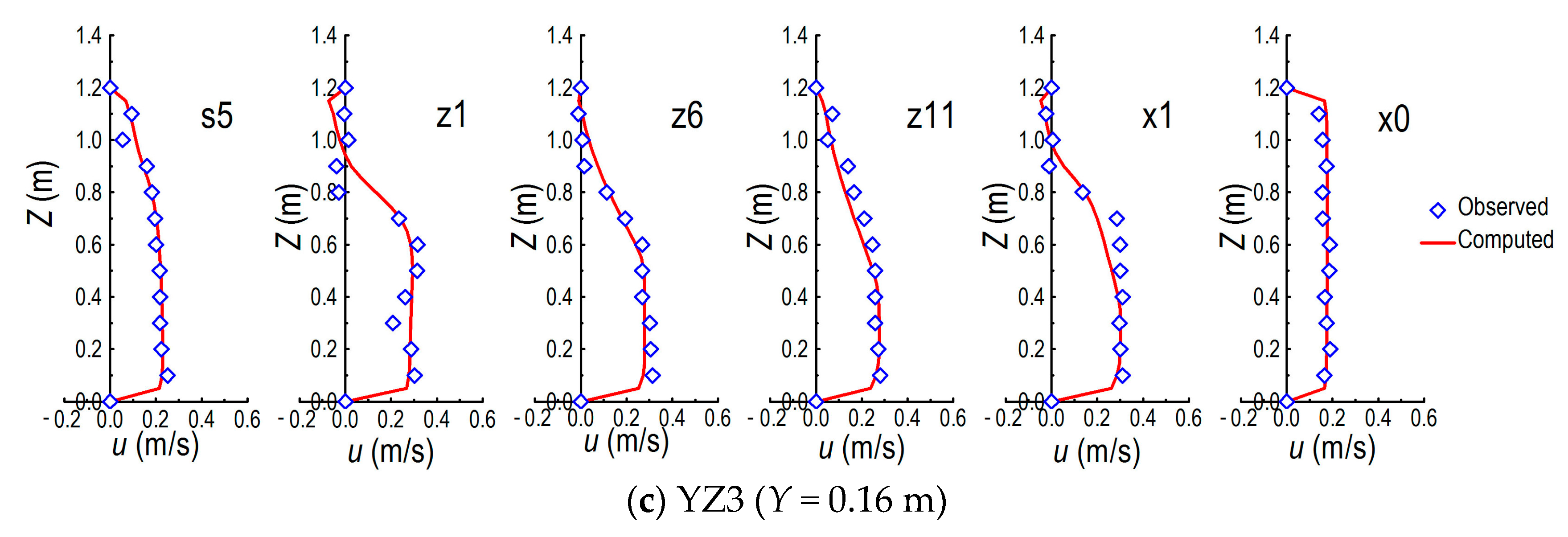
The cross-sections of s5, z1, z6, z11, x1 and x0 were selected as verification locations of the numerical model (shown in Figure 5). The comparisons of the u-velocity component along channel width Z at selected horizontal planes (i.e., selected water depths) are described in Figure 6. From the series of diagrams, good agreements between experiments and computations were observed. Table 3 and Table 4 compare the lengths (RL) and widths (RW) of the backflow zone downstream both spur dikes under conditions of YZ1, YZ2 and YZ3, respectively. It is noticed that all maximum relative errors (RE) were less than 5%, which indicate the consistency between numerical simulations and the corresponding flume experiments. Hence, the accuracy of numerical model was verified and could be employed for subsequent investigations on the spacing threshold of non-submerged twin spur dikes.
3.2. Identification of Spacing Threshold
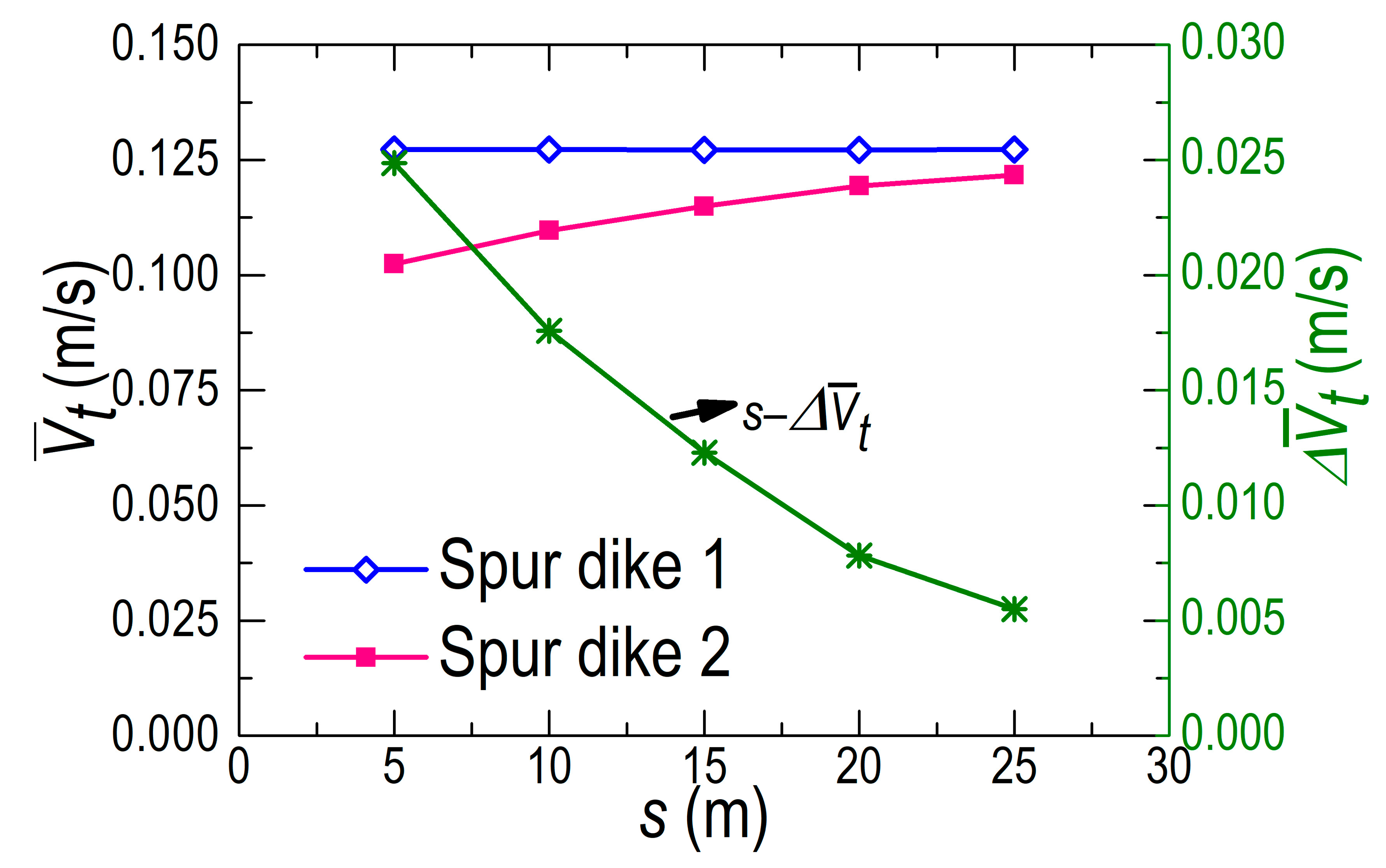
In order to classify “impact scale of spur dikes”, we proposed the concept of spacing threshold of non-submerged twin spur dikes with equal skew angle and ipsilateral layout in straight prism channel before [2], that is, the minimum spacing for maintaining the similarity of lateral distributions of magnitude velocity V at the cross-sections of twin spur dikes. When the dike spacing is larger than the threshold, the two spur dikes should be regarded as a large-scale group, otherwise a small-scale one. Figure 7 presents the comparisons of lateral distribution V (Y = 0.05 m) and at cross-sections A and B under different dike spacing s, where is the average of V along water depth. As indicated, the similarity of -patterns was almost the same to that of V-profiles at the both cross-sections. It means that the criterion of spacing threshold could be justified by whether the lateral distributions of at adjacent two spur dikes are similar or not. Figure 8 depicts the comparison of -patterns nearby the tips of twin spur dikes and relevant difference changes with dike spacing s, marked as and respectively. As the dike spacing s increased, the of spur dike 1 kept constant almost, while the of spur dike 2 gradually increased and approached the level of spur dike 1 until both tended the same level at . At this point, the velocities at cross-section B had recovered to the levels at cross-section A and the flow pattern around spur dike 2 was hardly affected by spur dike 1. Furthermore, the similarity of nearby the tips of twin spur dikes was ultimately determined by the criterion of spacing threshold, i.e., the minimum spacing of non-submerged twin spur dikes with equal skew angle and ipsilateral layout in straight prism channel when the of twin spur dikes were approximately coincident indicated in Figure 8 (The complete coincidence of of twin spur dikes was impossible due to frictional head loss and local head loss). In this research, the coincidence error was set as 0.05U, where U is the mean velocity at the inlet [8], and the coincidence of was given at 5 cm from the tips of both spur dikes.
3.3. Relations of Sc/b – Fr, B/b and B/h
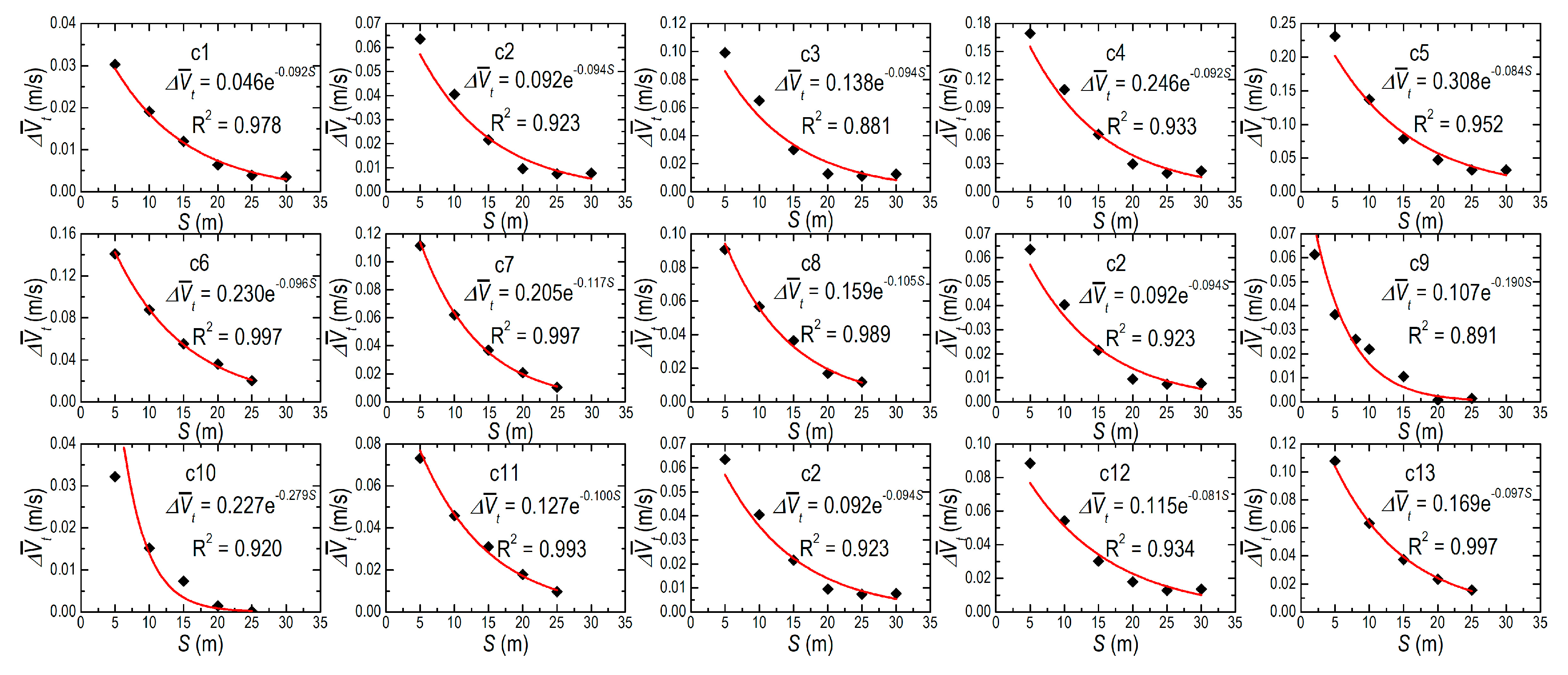
Figure 9 indicates the patterns of s– for all cases, i.e., c1, c2, c3, c4, c5, c6, c7, c8, c9, c10, c11, c12 and c13. For all cases, -values gradually decreased as dike spacing s increased and were less influenced with the further increase of s (e.g., s > 25 as indicated in Figure 9). The relations between s and can be expressed by negative exponential function for all cases. According to Figure 9 and the coincidence error of 0.05U mentioned above, the spacing thresholds Sc for all cases are obtained and listed in Table 5. As indicated, the spacing thresholds Sc for non-submerged twin spur dikes were less influenced and increased slightly with the increase of incoming flow rate Q with other parameters fixed (c1–c5 in Table 2). As B, h and Q fixed (c2, c6–c9 in Table 2), the spur dike played less influence on the flow as b decreased, i.e., the Sc of non-submerged twin spur dikes decreased as well.
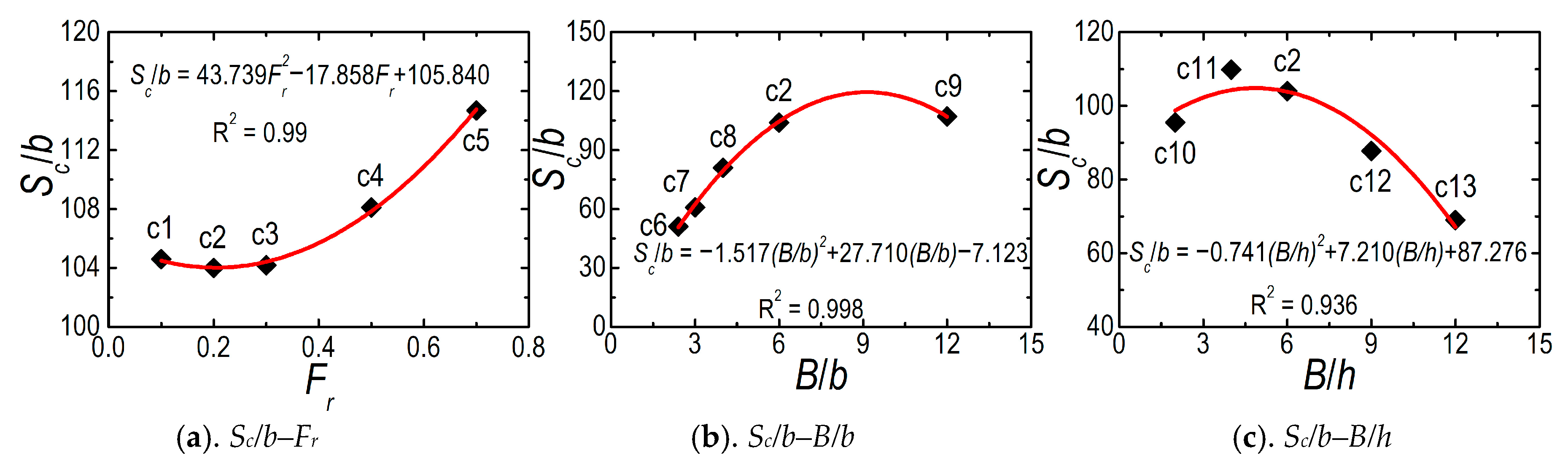
Figure 10 further provides the relationships between the relative spacing threshold Sc/b with the Froude number Fr, the relative dike length B/b, and the section width–depth ratio B/h. As indicated in Figure 10a, Sc/b slightly decreased first and then gradually increased as Fr increased with fixed B/b and B/h. However, Fr presents a minor influencing factor concerning the narrow range of Sc/b values. The relation of Sc/b–Fr can be approximately described by concave quadratic function. For Figure 10b, Sc/b increased first and then decreased slightly with B/b increasing under fixed Fr and B/h. The relation between B/b and Sc/b was approximated by the convex quadratic function. Moreover, the value range of Sc/b in Figure 10b was higher than that in Figure 10a, which indicates the strong impact of B/b on the Sc/b scale. For Figure 10c, Sc/b slightly increased first and then decreased sharply with the increase of B/h as Fr and B/b fixed. It indicates that the spur dike flow was easier to recover in wide-shallow water. Similarly, the relation between B/h and Sc/b could be again approximated by convex quadratic function.
3.4. Empirical Formula of Spacing Threshold
The results of Figure 10 are further regressed by statistical analysis software SPSS, and a general empirical formula of spacing threshold of non-submerged twin spur dikes was obtained in multiple-regression equation listed as below:
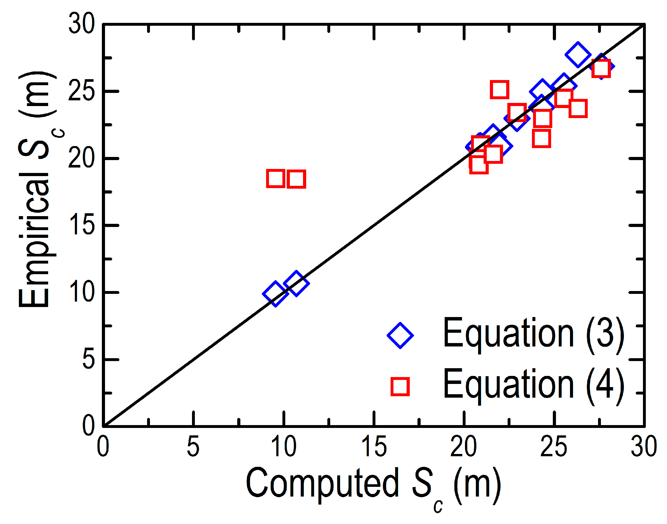
To examine the fitting effect of Equation (3), the calculated values Sc for cases c1–c13 from Equation (3) were compared with corresponding CFD results and shown in Figure 11. Good agreement between two data sets illustrated a satisfactory fitting effect of Equation (3). Similarly, in a previous study [17], we proposed an empirical formula, i.e., Equation (4), to estimate the spacing threshold of non-submerged twin spur dikes with ipsilateral layout as:
The performance comparison between Equations (3) and (4) is expressed in Figure 11. The figure indicates that Equation (3) offers higher accuracy than Equation (4), especially in the range of small Sc values. The reason causing such is that the conditions to acquire Equation (3) cover wider scope than that to obtain Equation (4). Therefore, considering that the conditions involved in this study have approached the ultimate range, Equation (3) is recommended as the final empirical formula of spacing threshold of non-submerged twin spur dikes with ipsilateral and orthogonal layout in straight rectangular channel.
According to the ranges of parameters Fr = 0.1–0.7, B/b = 2.4–12 and B/h = 2–12 in current research, the minimum and maximum values of Equation (3) can be obtained through generalized genetic algorithms [31] optimization respectively, i.e., (Sc/b)min = 24 (Fr = 0.204, B/b = 2.60, B/h = 11.36) and (Sc/b)max = 130 (Fr = 0.665, B/b = 9.02 and B/h = 4.87) or Sc = 24b–130b alternatively. This range of Sc is wider than the recovery lengths obtained by previous researchers, e.g., Sc = 38b–52b (Nanjing Hydraulic Research Institute, Nanjing, China), Sc = 40b–60b (Tianjin Research Institute for Water Transport Engineering, Tianjin, China) and Sc = 30b–70b (Department of Transportation of Hunan Province, China) cited by [32]. Such status implies that, on one hand, existing researches have not yet achieved full agreement on awareness of the recovery area in the downstream of spur dike; on the other hand, Equation (3) obtained by this investigation possesses more inclusive than previous formula.
However, it must be pointed out that: by definition, the spacing threshold of twin spur dikes used in this study was a little longer than the recovery length of single spur dike declared by [32]. When the spacing between neighboring upstream and downstream spur dikes reached the threshold, the location of downstream dike exceeded the recovery range of upstream dike and was hardly affected by the upstream one. Under the circumstances, the adjacent two spur dikes on the river system were regarded as the spur dike group in large-scale.
4. Conclusions
Both flume experimental study and numerical simulations on non-submerged twin spur dikes with ipsilateral and orthogonal layout were carried out and reported in this paper. Based on the concept of spacing threshold and its dimensionless equations of non-submerged twin spur dikes with ipsilateral and orthogonal layout implemented in straight rectangular channel, the models were used for quantitative investigation of spacing thresholds. The following conclusions could be drawn:
- (a)
- The similarity of the average velocity along the water depth nearby the tips of twin spur dikes was determined by the spacing threshold, i.e., the minimum spacing where the of twin spur dikes were approximately coincident. This criterion is also suitable for the case of non-submerged twin spur dikes with equal skew angle and ipsilateral layout in straight prism channel.
- (b)
- For straight rectangular channel, the influencing factors of the relative spacing threshold Sc/b of non-submerged twin spur dikes with ipsilateral and orthogonal layout include Fr, B/b and B/h. Among these three factors, Fr presented the least impact on the scale of Sc/b.
- (c)
- Under fixed Fr and B/h, Sc/b increased first and then decreased slightly as B/b increased. The relation of Sc/b–B/b was approximately described by the convex quadratic function. Similarly, with fixed Fr and B/b, Sc/b slightly increased first and then decreased sharply as B/h increased. The pattern of Sc/b–B/h could be approximated by the convex quadratic function too.
- (d)
- A generalized, normalized empirical formula of spacing threshold was obtained in this study, which presented applicable only to non-submerged twin spur dikes with ipsilateral and orthogonal layout in straight rectangular channel due to generalization and simplification of the flow for non-submerged twin spur dikes employed. The formula presented good, reliable accuracy with wider recovery range concurrently, i.e., Sc = 24b–130b.
Although the outcomes, obtained in this research, were idealized and deviated from the situation in reality, they had established a good foundation for further investigations. These conclusions could be used to understand the impact scale and characteristics of water-sediment in river systems with spur dike groups implemented, provided references to assess the health of river systems, arranged spur dikes in large- and/or small-scales accordingly, and truly realized the quantitative classification of impact scale of spur dike groups on natural river systems in future.
Author Contributions
The research scheme was a joint effort of Z.G. and W.-Z.L., Z.G. and X.C. were responsible for carrying out the numerical investigations and experimental measurements and analyzing the computed data. Z.G. and X.C. wrote the first draft of the paper, and W.-Z.L., Z.G., and Q.G. contributed to reviewing and editing the manuscript. All authors have read and agreed to the published version of the manuscript.
Funding
This research was funded by the National Natural Science Foundation of China (Grant No. 51579216), the Strategic Research Grant, City University of Hong Kong (Projects No. 7004867), the National Key Research and Development Program of China (No. 2016YFC0401500), 7th sub-topic (No. 2016YFC0401507), 3rd sub-topic (No. 2016YFC0401503).
Acknowledgments
The authors thank the editors and two anonymous reviewers for their constructive suggestions and comments for improvement of the paper.
Conflicts of Interest
The authors declare no conflict of interest.
Nomenclature
| Fr | Froude number |
| B/b | relative dike length |
| B/h | section width-depth ratio |
| Sc/b | relative spacing threshold |
| U | mean velocity of approaching flow |
| k | turbulent kinetic energy |
| ε | turbulent dissipation rate |
| s | dike spacing |
| RL | length of backflow zone |
| RW | width of backflow zone |
| X-axis | direction along the main flow |
| Y-axis | direction along the water depth |
| Z-axis | direction parallel to the spur dike length |
| V | magnitude velocity |
| Sc | spacing threshold |
| b | dike length |
| B | channel width |
| Q | flow rate of approaching flow |
| h | water depth |
| ρ | density of water |
| g | acceleration of gravity |
| RE | relative error |
| u | velocity component in X direction |
| v | velocity component in X direction |
| w | velocity component in X direction |
| average of V along water depth | |
| nearby the tip of spur dike | |
| relevant difference changes of between twin spur dikes |
References
- Pinter, N.; Jemberie, A.; Remo, J.; Heine, R.; Ickes, B. Cumulative impacts of river engineering, Mississippi and lower Missouri Rivers. River Res. Appl. 2010, 26, 546–571. [Google Scholar] [CrossRef]
- Cao, X.; Gu, Z. Three classification criteria and their comparison impact scale between double non-submerged spur dikes. J. Zhejiang Univ. Eng. Sci. 2015, 49, 200–207. [Google Scholar] [CrossRef]
- James, R. Defining and measuring river health. Freshw. Biol. 1999, 41, 221–234. [Google Scholar] [CrossRef] [Green Version]
- He, Y.; Li, Y.; Wu, D.; Deng, J. Flow and sediment process versus river health. J. Hydraul. Eng. 2006, 37, 1354–1359. [Google Scholar] [CrossRef]
- Richard, H.; Martin, C. What is river health? Freshw. Biol. 1999, 41, 197–209. [Google Scholar] [CrossRef] [Green Version]
- Wohl, E. Identifying and mitigating dam-induced declines in river health: Three case studies from the western United States. Int. J. Sediment Res. 2012, 27, 271–287. [Google Scholar] [CrossRef]
- Ohmoto, T.; Hirakawa, R.; Koreeda, N. Effects of water surface oscillation on turbulent flow in an open channel with a series of spur dikes. Hydraul. Meas. Exp. Methods 2002, 2002, 1–10. [Google Scholar] [CrossRef]
- Ying, Q.; Jiao, Z. Hydraulics of Spur Dike; Ocean Press: Beijing, China, 2004. [Google Scholar]
- Kuhnle, R.; Jia, Y.; Alonso, C. Measured and simulated flow near a submerged spur dike. J. Hydraul. Eng. 2008, 134, 916–924. [Google Scholar] [CrossRef]
- Duan, J.; He, L.; Fu, X.; Wang, Q. Mean flow and turbulence around experimental spur dike. Adv. Water Resour. 2009, 32, 1717–1725. [Google Scholar] [CrossRef]
- Acharya, A.; Duan, J. Three dimensional simulation of flow field around series of spur dikes. In Proceedings of the World Environmental and Water Resources Congress 2011: Bearing Knowledge for Sustainability, Palm Springs, CA, USA, 22–26 May 2011; pp. 2085–2094. [Google Scholar] [CrossRef] [Green Version]
- Zhang, X.; Wang, P.; Yang, C. Experimental study on flow turbulence distribution around a spur dike with different structure. Procedia Eng. 2012, 28, 772–775. [Google Scholar] [CrossRef] [Green Version]
- Zhang, H.; Nakagawa, H. Scour around spur dyke: Recent advances and future researches. Disaster Prev. Res. Inst. Ann. 2008, 51, 633–652. [Google Scholar]
- Acharya, A.; Acharya, A.; Duan, J. Three dimensional simulation of flow field around series of spur dikes. Int. Refereed J. Eng. Sci. 2013, 2, 36–57. [Google Scholar]
- Tang, X.; Ding, X.; Chen, Z. Large eddy simulations of three-dimensional flows around a spur dike. Tsinghua Sci. Technol. 2006, 11, 117–123. [Google Scholar] [CrossRef]
- Azinfar, H. Flow Resistance and Associated Backwater Effect Due to Spur Dikes in Open Channels. Ph.D. Thesis, University of Saskatchewan, Saskatoon, SK, Canada, 2010. Available online: http://ecommons.usask.ca/bitstream/handle/10388/etd-03012010-130940/HosseinAzinfarPHDThesis.pdf (accessed on 25 July 2015).
- Cao, X.; Gu, Z.; Tang, H. Study on spacing threshold of nonsubmerged spur dikes with alternate layout. J. Appl. Math. 2013, 1–8. [Google Scholar] [CrossRef]
- Mayerle, R.; Wang, S.; Toro, F. Verification of a three-dimensional numerical model simulation of the flow in the vicinity of spur dikes. J. Hydraul. Res. 1995, 33, 243–256. [Google Scholar] [CrossRef]
- Cui, Z.; Zhang, X. Flow simulation of spur dike using 3-D turbulent model. Eng. J. Wuhan Univ. 2006, 39, 15–20. [Google Scholar] [CrossRef]
- Cui, Z.; Zhang, X. Flow and sediment simulation around spur dike with free surface using 3-D turbulent model. J. Hydrodyn. 2006, 18, 237–244. [Google Scholar] [CrossRef]
- Chen, Z.; Hei, P.; Ding, X. Division and flow scale investigation of circulation zone around spur dike. Adv. Water Sci. 2008, 19, 613–617. [Google Scholar] [CrossRef]
- Azinfar, H.; Kells, J. Backwater prediction due to the blockage caused by a single, submerged spur dike in an open channel. J. Hydraul. Eng. 2008, 134, 1153–1157. [Google Scholar] [CrossRef]
- Azinfar, H.; Kells, J. Flow resistance due to a single spur dike in an open channel. J. Hydraul. Res. 2009, 47, 755–763. [Google Scholar] [CrossRef]
- Tominaga, A.; Matsumoto, D. Diverse Riverbed Figuration by Using Skew Spur-Dike Groups. In Proceedings and Monographs in Engineering, Water and Earth Sciences, Proceedings of the International Conference on Fluvial Hydraulics, Lisbon, Portugal, 6–8 September 2006; Taylor & Francis: London, UK, 2006; pp. 683–691. Available online: http://apps.webofknowledge.com/full_record.do?product=WOS&search_mode=GeneralSearch&qid=1&SID=N2iurXVlKjBqvw2ejd5&page=1&doc=1 (accessed on 25 July 2015).
- Gao, X.; Liu, H.; Hua, G.; Wang, Z. Rational spacing characters of double permeable spur. J. Shihezi Univ. Nat. Sci. 2010, 28, 614–617. [Google Scholar] [CrossRef]
- Li, Z.; Liao, X. The cumulative impact of river construction projects on flood control. J. Hydro-Sci. Eng. 2011, 121–125. [Google Scholar] [CrossRef]
- Molls, T.; Chaudhry, M.; Khan, K. Numerical simulation of two-dimensional flow near a spur-dike. Adv. Water Resour. 1995, 18, 227–236. [Google Scholar] [CrossRef]
- Fluent Inc. FLUENT 6.3 User’s Guide. 2006. Available online: https://www.sharcnet.ca/Software/Fluent6/pdf/ug/flug.pdf (accessed on 25 July 2015).
- Karvinen, A.; Ahlstedt, H. Comparison of turbulence models in case of three-dimensional diffuser. In Proceedings of the Open Source CFD International Conference, Berlin, Germany, 4–5 December 2008; p. 17. Available online: http://powerlab.fsb.hr/ped/kturbo/openfoam/Berlin2008/PosterSession/OSCIC-08_KarvinenAku.pdf (accessed on 25 July 2015).
- Buckingham, E. On physically similar systems; illustrations of the use of dimensional equations. Phys. Rev. 1914, 4, 345–376. [Google Scholar] [CrossRef]
- Gu, Z. Generalized genetic algorithms and its application to identifying flow parameters. Syst. Eng.-Theory Prac. 2006, 26, 133–137. [Google Scholar] [CrossRef]
- Ying, Q. Flow pattern near the submerged spur dike. J. Hohai Univ. Nat. Sci. 1995, 4, 62–68. [Google Scholar] [CrossRef]
Figure 1.
The spur dike groups on river systems (notes: (a). Spur dikes to improve both banks of Rhine River, USA; (b). Spur dikes to reinforce banks of Xijiang River, Guangdong, China; (c). Spur dikes as training works for navigation in Odra River, Poland).
Figure 1.
The spur dike groups on river systems (notes: (a). Spur dikes to improve both banks of Rhine River, USA; (b). Spur dikes to reinforce banks of Xijiang River, Guangdong, China; (c). Spur dikes as training works for navigation in Odra River, Poland).

Figure 2.
Non-submerged twin spur dikes with ipsilateral and orthogonal layout sketch.

Figure 3.
Local refined grids near spur dike.

Figure 4.
Multifunction flume facility and measuring instruments.

Figure 5.
Distribution of measured cross-sections and points.

Figure 6.
Comparisons of u-profiles between observed and computed data. (a) YZ1 (Y = 0.09 m); (b) YZ2 (Y = 0.09 m); (c) YZ3 (Y = 0.16 m).
Figure 6.
Comparisons of u-profiles between observed and computed data. (a) YZ1 (Y = 0.09 m); (b) YZ2 (Y = 0.09 m); (c) YZ3 (Y = 0.16 m).


Figure 7.
Comparison of lateral distributions V (Y = 0.05 m) and at A and B with different spacing levels.
Figure 7.
Comparison of lateral distributions V (Y = 0.05 m) and at A and B with different spacing levels.

Figure 8.
Relations of s– and s–.

Figure 9.
Profiles of s– for Cases c1–c13.

Figure 10.
Relations of Sc/b vs. Fr, B/b and B/h. (a). Sc/b–Fr; (b). Sc/b–B/b; (c). Sc/b–B/h.

Figure 11.
Comparison of the empirical formula and computational fluid dynamics (CFD) results on Sc.
Figure 11.
Comparison of the empirical formula and computational fluid dynamics (CFD) results on Sc.


Table 1.
Verification conditions.
| No. | Q (m3/s) | b (m) | h (m) | s (m) |
|---|---|---|---|---|
| YZ1 | 0.0485 | 0.2 | 0.15 | 4.8 |
| YZ2 | 0.0416 | 0.4 | 0.15 | 4.8 |
| YZ3 | 0.0618 | 0.3 | 0.3 | 4.8 |
Table 2.
Simulation conditions of cases.
| No. | B (m) | b (m) | h (m) | Q (m3/s) | Fr | B/h | B/b |
|---|---|---|---|---|---|---|---|
| Case 1 (c1) | 1.2 | 0.2 | 0.2 | 0.0336 | 0.1 | 6 | 6 |
| Case 2 (c2) | 1.2 | 0.2 | 0.2 | 0.0672 | 0.2 | 6 | 6 |
| Case 3 (c3) | 1.2 | 0.2 | 0.2 | 0.1008 | 0.3 | 6 | 6 |
| Case 4 (c4) | 1.2 | 0.2 | 0.2 | 0.168 | 0.5 | 6 | 6 |
| Case 5 (c5) | 1.2 | 0.2 | 0.2 | 0.2352 | 0.7 | 6 | 6 |
| Case 6 (c6) | 1.2 | 0.5 | 0.2 | 0.0672 | 0.2 | 6 | 2.4 |
| Case 7 (c7) | 1.2 | 0.4 | 0.2 | 0.0672 | 0.2 | 6 | 3 |
| Case 8 (c8) | 1.2 | 0.3 | 0.2 | 0.0672 | 0.2 | 6 | 4 |
| Case 2 (c2) | 1.2 | 0.2 | 0.2 | 0.0672 | 0.2 | 6 | 6 |
| Case 9 (c9) | 1.2 | 0.1 | 0.2 | 0.0672 | 0.2 | 6 | 12 |
| Case 10 (c10) | 0.6 | 0.1 | 0.3 | 0.0618 | 0.2 | 2 | 6 |
| Case 11 (c11) | 1.2 | 0.2 | 0.3 | 0.1235 | 0.2 | 4 | 6 |
| Case 2 (c2) | 1.2 | 0.2 | 0.2 | 0.0672 | 0.2 | 6 | 6 |
| Case 12 (c12) | 1.8 | 0.3 | 0.2 | 0.1009 | 0.2 | 9 | 6 |
| Case 13 (c13) | 2.4 | 0.4 | 0.2 | 0.1345 | 0.2 | 12 | 6 |
Table 3.
Comparison of RL and RW between observed and computed (spur dike 1).
| No. | Length of Backflow Zone RL (m) | Width of Backflow Zone RW (m) | ||||
|---|---|---|---|---|---|---|
| Flume Test | CFD | RE (%) | Flume Test | CFD | RE (%) | |
| YZ1 | 1.76 | 1.7052 | 3.11 | 0.3127 | 0.302 | 3.42 |
| YZ2 | / | / | / | 0.5596 | 0.5847 | 4.49 |
| YZ3 | 2.4 | 2.508 | 4.5 | 0.4297 | 0.4442 | 3.37 |
Note: RL of YZ2 beyond the dike spacing.
Table 4.
Comparison of RL and RW between observed and computed (spur dike 2).
| No. | Length of Backflow Zone RL (m) | Width of Backflow Zone RW (m) | ||||
|---|---|---|---|---|---|---|
| Flume Test | CFD | RE (%) | Flume Test | CFD | RE (%) | |
| YZ1 | 1.21 | 1.1886 | 1.78 | 0.245 | 0.2416 | 1.39 |
| YZ2 | 2.0 | 1.9414 | 2.93 | 0.44 | 0.4511 | 2.52 |
| YZ3 | 1.8 | 1.7502 | 2.77 | 0.35 | 0.339 | 3.14 |
Table 5.
Spacing thresholds for c1–c13.
| c1 | c2 | c3 | c4 | c5 | c6 | c7 | c8 | c9 | c10 | c11 | c12 | c13 | |
|---|---|---|---|---|---|---|---|---|---|---|---|---|---|
| Sc (m) | 20.919 | 20.798 | 20.838 | 21.621 | 22.938 | 25.539 | 24.355 | 24.298 | 10.704 | 9.550 | 21.972 | 26.323 | 27.610 |
© 2020 by the authors. Licensee MDPI, Basel, Switzerland. This article is an open access article distributed under the terms and conditions of the Creative Commons Attribution (CC BY) license (http://creativecommons.org/licenses/by/4.0/).
Share and Cite
MDPI and ACS Style
Gu, Z.; Cao, X.; Gu, Q.; Lu, W.-Z. Exploring Proper Spacing Threshold of Non-Submerged Spur Dikes with Ipsilateral Layout. Water 2020, 12, 172. https://doi.org/10.3390/w12010172
AMA Style
Gu Z, Cao X, Gu Q, Lu W-Z. Exploring Proper Spacing Threshold of Non-Submerged Spur Dikes with Ipsilateral Layout. Water. 2020; 12(1):172. https://doi.org/10.3390/w12010172
Chicago/Turabian StyleGu, Zhenghua, Xiaomeng Cao, Qiaoya Gu, and Wei-Zhen Lu. 2020. "Exploring Proper Spacing Threshold of Non-Submerged Spur Dikes with Ipsilateral Layout" Water 12, no. 1: 172. https://doi.org/10.3390/w12010172
Note that from the first issue of 2016, this journal uses article numbers instead of page numbers. See further details here.