Numerical Analysis of the Effects of Crack Characteristics on the Stress and Deformation of Unsaturated Soil Slopes


State Key Laboratory of Hydraulics and Mountain River Engineering, College of Water Resource and Hydropower, Sichuan University, Chengdu 610065, China
*
Author to whom correspondence should be addressed.
Water 2020, 12(1), 194; https://doi.org/10.3390/w12010194
Submission received: 23 October 2019
/
Revised: 14 December 2019
/
Accepted: 7 January 2020
/
Published: 10 January 2020
(This article belongs to the Section Hydraulics and Hydrodynamics)
Abstract
:Cracks induced by evaporation or rainfall have a great influence on the stability of unsaturated soil slopes, which can lead to landslides during the rainfall process. In order to study the effect of crack characteristics on the evolution of stress and deformation of unsaturated soil slopes, a series of numerical analyses under different conditions were performed using a coupled elastoplastic finite element program that we developed for unsaturated soil. When carrying out the numerical analyses, the effective stress for unsaturated soil proposed by Bishop and an elastoplastic double-hardening constitutive model for the soil skeleton were employed. The varying parameters, including the crack location, the discharge speed, evaporation rate, infiltration rate, and tensile strength, were investigated to study the coupling process of pore water pressure and deformation in the process of evaporation and rainfall infiltration. The numerical results showed that the minimum pore water pressure of the soil slope at the end of evaporation/rainfall decreased gradually and the crack width increased gradually as the crack set closer to the slope; the larger the discharge speed of pore air, the greater the crack width. With the increase in the evaporation rate, the pore water pressure of the soil slope reduced and the crack initiated earlier and became wider. As the infiltration rate increased, the pore water pressure of the soil slope and the crack width increased, but the decreasing duration became shorter. The change of tensile strength had little effect on the pore water pressure, but the development of the crack width changed with evaporation and rainfall infiltration.
1. Introduction
Slope instability is related to many factors, such as geological structure, geotechnical properties, climatic conditions, topography, surface water effects, groundwater activities, human engineering activities, and earthquakes. Among them, rainfall infiltration is one of the most important conditions that cause slope instability. The occurrence and development of slope failures, such as collapse, landslide, and debris flow, are mostly controlled by factors such as rainfall infiltration [1]. During the process of evaporation and rainfall infiltration, the development and closure of slope cracks in unsaturated soils may be induced, which will have a great influence on the evolution of stress and deformation of the unsaturated soil slope.
Due to the complexity of field tests on unsaturated soil slopes, there is scant research in this area. Blatz et al. [2] initiated a project including a field investigation program, a laboratory testing program, and advanced numerical modeling to identify the cause of two shallow slope failures. A residual soil slope in Singapore was equipped with pore water pressure, water content, and rainfall measuring devices, where studies were carried out under natural and simulated rainfalls [3]. Timpong et al. [4] described the development of a new in-flight ground water table control system in a centrifuge, which can be used to investigate the mechanism of slope failure induced by ground water table changes. Ng et al. [5] investigated the effects of pole transpiration on rainfall-induced slope hydrology through centrifuge model tests by using real branch cuttings. Jeong et al. [6] investigated rainfall-induced landslides on partially saturated soil slopes using the 2011 Umyeonsan landslides at the center of Seoul, Korea and then carried out an integrated analysis of rainfall-induced landslides through laboratory tests, field tests, and numerical analysis. Experimental works and numerical analysis were conducted to determine the critical condition of the slope stability due to the evolution of shear strength parameters [7]. Ismail et al. [8] described a study in which simulated rainfall events were used with a two-dimensional soil column to study the response of unsaturated soil behavior based on different slope angles.
In order to deal with complex initial and boundary conditions, numerical methods have been applied more often in stress and deformation analyses of unsaturated soil slopes [9,10,11,12,13,14,15]. To investigate the influence of various rainfall events and initial ground conditions on transient seepage and, hence, slope stability, a parametric study was carried out by Ng et al. [16]. Numerical models were used to study how infiltration into a slope varied with respect to rainfall intensity and how this infiltration affected the stability of the slope [17]. A safety factor was calculated based on the smoothed stress field obtained from finite element analysis, and an optimization technique was used to search for a critical slip surface [18]. Shen [19] used the simplified consolidation theory of unsaturated soil to simulate the development of pore pressure and deformation of a canal slope excavated in unsaturated expansive soil in Zaoyang City during artificial rainfalls. Based on the theory of unsaturated soil, the seepage and stability of a slope under rainfall infiltration were studied with the finite element method [20]. A multiphase coupled elasto-viscoplastic finite element analysis formulation, based on the theory of porous media, was used to describe the rainfall infiltration process into a one-dimensional soil column [21]. Zhan et al. [22] developed an analytical solution for simulating rainfall infiltration into an infinite unsaturated soil slope based on the general partial differential equation for water flow through unsaturated soils. Liu et al. [23] used a coupled elastoplastic finite element analysis based on simplified consolidation theory for unsaturated soils to investigate the coupling processes of water infiltration and deformation. A numerical analysis of the relationship between three rainfall patterns and the anisotropic ratios was designed to investigate the effects of the anisotropic ratio on the stability of slopes using the reliability index approach [24]. A novel approach developed by Arairo et al. [25] to predict the behavior of unsaturated soils was discussed to investigate the effect of rainfall events on the stability of soil slopes. With a suction-stress-based effective stress representation, Vahedifard et al. [26] performed a stability analysis of unsaturated engineered and natural slopes effectively in the same manner as the classical limit equilibrium (LE) methodologies. Kim and Jeong [27] presented a numerical investigation to study the hydromechanical response of a shallow landslide in unsaturated slopes subjected to rainfall infiltration using a coupled model. Gofar and Rahardjo [28] presented results of saturated and unsaturated stability analyses of typical residual slopes subjected to rainfall infiltration, which corresponded to a 50 year rainfall return period.
Some researchers [29,30] have studied crack-containing unsaturated soil slopes. Finite element simulation was used to analyze the influences of cracks’ position, depth, and seepage characteristics on a slope’s rainfall infiltration [31]. Considering the cracking of expansive soils, the seepage characteristics of expansive soil slope were studied under the circumstance of rainfall infiltration [32]. Based on the generalized consolidation theory of unsaturated soils, coupled analysis of deformation of the soil skeleton and the movement of pore water and pore air in stiff fissured clay and swelling soil were performed for a selected slope [33]. Liu et al. [34] proposed a new analytical model for describing the progressive slow movement of natural slopes based on the relationship between velocity and the viscoplastic strain rate. Wang [35] derived the formulae of secondary crack spacing and secondary trend crack spacing after stress analysis. Li [36] investigated crack development, characterized crack geometrical parameters under natural atmosphere conditions by field tests, and then studied the permeability tensor and REV (representative element volume) for saturated soils containing random crack networks through numerical simulation. The dynamic development of cracks in expansive soil during drying and wetting has been measured in the laboratory to study the hydraulic properties of cracks by Cao et al. [37].
From the abovementioned work, we can see that though some in situ experiments and numerical analyses have been carried out on the coupling process of stress and deformation of unsaturated soil slopes, few studies have been done on the influence of crack characteristics on stress and deformation, which can affect the stability of unsaturated soil slopes and was investigated here. In this study, the effects of crack characteristics, including the location of the crack, discharge speed, evaporation rate, infiltration rate, and tensile strength, on the stress and deformation of unsaturated soil slopes were explored numerically by using a coupled finite element method developed by the authors.
2. Materials and Methods
Based on the simplified consolidation theory of unsaturated soil proposed by Shen [38], the coupling elastoplastic finite element analysis method is used to analyze the seepage–deformation coupling process of unsaturated soils here. By using the reduced suction and elastoplastic constitutive equations, the simplified consolidation theory of unsaturated soils is incorporated into the finite element program in Fortran. And the development of pore water pressure and deformation under evaporation and rainfall infiltration conditions can be calculated through this numerical method.
2.1. Simplified Consolidation Theory for Unsaturated Soils
2.1.1. Effective Stress Formula
Bishop’s formula was used to represent the principle of effective stress for unsaturated soils:
where is the effective stress, is the total stress, is the pore air pressure, is the pore water pressure, the term is called the matrix suction, and is called the coefficient of reduced suction. The coefficient of reduced suction varies with the matrix suction in the manner proposed here as follows:
where is the air entry value, and is a material constant.
2.1.2. Pore Air Pressure Assumption
We defined
as the ratio of the pore air of a unit soil element to signify the air content in the pores of a soil element within a unit volume, where is the porosity, is the Henry coefficient of solubility, and is the degree of saturation of the soil element. Based on Boyle’s law, , and the air pressure in the pores can be obtained:
where is the initial ratio of the pore air of a unit soil element, and is the atmospheric pressure. Under the conditions that the air in the pores is discharged partially, it was assumed that the mass of air discharged per unit time is , and we defined the discharge speed of pore air as follows:
So, we can obtain the expression for the increment of pore air pressure as follows:
If is constant, by integrating Equation (6), we have
When the air cannot discharge, , and Equation (7) can be reduced to Equation (4); when , , which corresponds to the conditions that air is discharged completely.
2.1.3. Governing Equations
If the effect of temperature is not considered and the flow of dissolved air in the pore water and vapor in the pore air is ignored, the consolidation equations for unsaturated soils are as follows:
- Equilibrium equations:
- Continuous equations of pore water:
- Continuous equations of pore air:
- The relationship of effective stress displacement:
- The relationship of the saturation matrix suction:
- The coefficient of permeability of the pore water:
- The coefficient of permeability of pore air:where , is the increment of total stress, represents the increments of effective stress, is the porosity, is the density of pore water, is the density of air in the pore, is the gravitational acceleration, is the increment of effective stress, is the matrix of stress–strain, and is the increment of displacement.
2.1.4. Simplified Consolidation Equations for Unsaturated Soils in 2D
In consideration of the increment of total stress from Equation (1) can be described as follows:
where and . Substituting the above equations into Equation (8), we have:
where is the increment of the horizontal displacement, is the increment of the vertical displacement, are the increments of loads in the horizontal direction, are the increments of loads in the vertical direction, and … are the elements of the elastoplastic matrix of stress–strain. The continuous equation of pore water is formulated as follows:
where is the coefficient of permeability in the horizontal direction and is the coefficient of permeability in the vertical direction,
2.2. Constitutive Equations
2.2.1. Double-Hardening Model for Soil Skeleton
Regardless of the influence of temperature, the double-hardening elastoplastic model for saturated soils [39] was used to describe the mechanical features of the soil skeleton of unsaturated soils.
Set . The yield function of the model is expressed as follows:
where , and is the parameter of yield function; when the shape of the yield surface is close to an ellipse. and are the two hardening parameters, which evolve with plastic volumetric strain and plastic shear strain , respectively, as follows:
where is the slope of the compressional curve, is the slope of the rebound curve, and is the reference pressure when . Equation (20) is in the same form as the hardening parameter of the original Cam-clay model. In Equation (21), where is internal frictional angle, and and are two other parameters that can be determined by an unloading triaxial compression test, in which the axial load is kept constant and the confining pressure is reduced gradually.
Assuming that the flow rule is associated, the plastic strain increment can be determined by the use of elastic-plastic theory as follows:
or
where is the plastic multiplier, which can be derived from the consistency conditions:
Substituting for the plastic volumetric strain increment and the plastic shear strain increment in Equations (23) and (24), is obtained as follows:
where the hardening modulus is
2.2.2. Soil-Water Characteristic Curve
The soil-water characteristic curve is divided into two sections. When the value of matrix suctions is smaller than that of the air entry suction the soil can be assumed to be quasi-saturated and the degree of saturation of quasi-saturated soil is assumed to be so the degree of saturation can be expressed by using the Hilf formulation.
When the value of matrix suction s is greater than that of the air entry suction the degree of saturation is computed as follows [40]:
During the process of drying shrinkage or absorbing water, the parameters , and may be different. By the derivation of Equation (28), we have
The coefficient of permeability of unsaturated soils is calculated as follows:
where is the coefficient of permeability of saturated soils, and is constant. When
2.3. Formulations of the Finite Element Equations
Isoperimetric elements were implemented with eight-node interpolating functions for the displacements and four-node interpolating functions for the pore water pressures, which can be expressed as follows:
where , and are the nodal variables at nodal point The weak forms of Equations (31)–(33) are discretized in space and solved by the finite element method as follows:
where is the total number of nodal points; , and are the load increments and flux increment at node respectively; is the initial value of the water head at node and is an integral parameter ( was used here). The coefficients in the upper equations are as follows:
and
where (saturated) or (unsaturated).
2.4. Computational Model
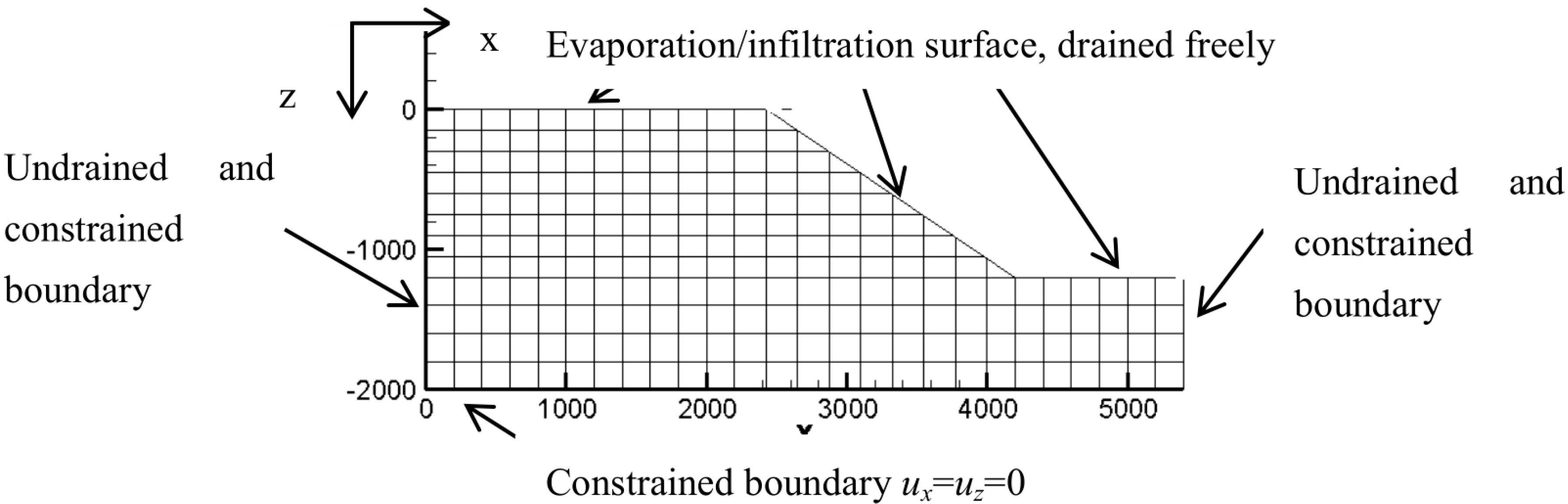
The seepage–deformation processes under evaporation and rainfall infiltration conditions were simulated for an unsaturated soil slope which was 20 m in depth and 54 m in width using the coupled elastoplastic finite element program in Fortran. The computational mesh and boundary conditions are shown in Figure 1.
For the lateral surfaces, there were undrained and constrained boundaries. For the bottom surface, also the surface of the groundwater table, there was a constrained boundary; the pore water pressure was zero all the time with the surface of the groundwater table. For the upper surfaces composed of three surfaces, it drained freely, and evaporation/rainfall occurred on these surfaces.
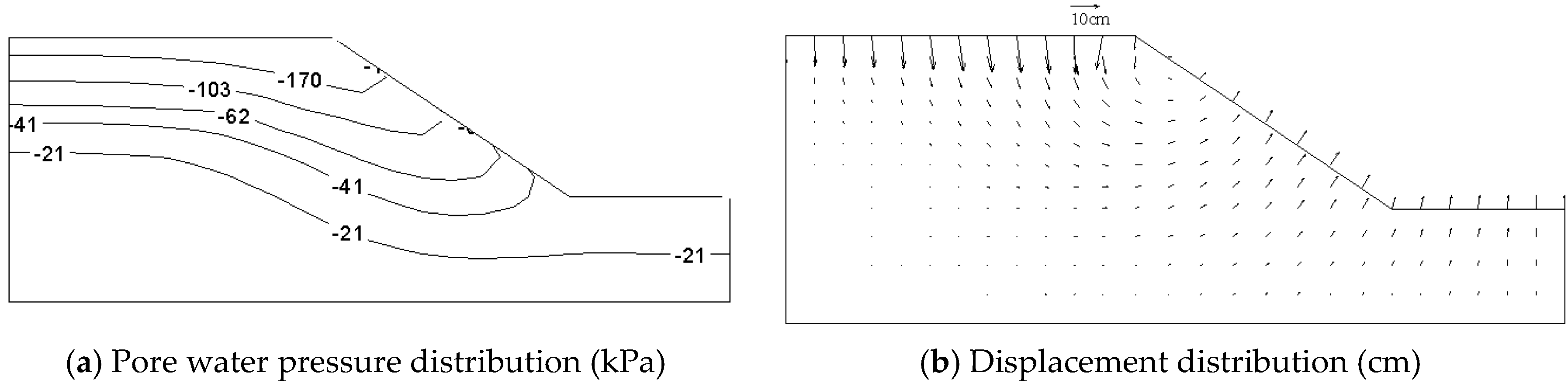
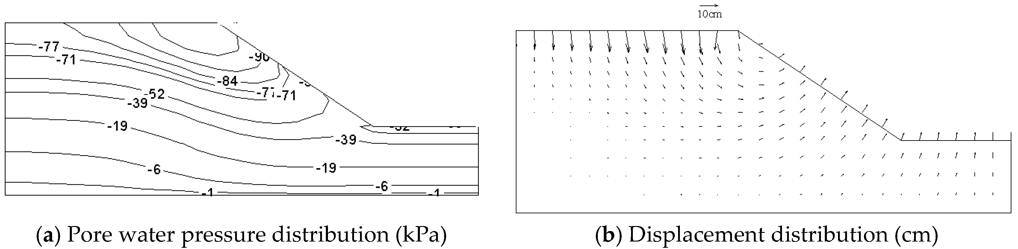
When t = 0, the soil slope was saturated and in equilibrium with the weight stress state. The calculation simulated a long geological process without ground pressure and formed a soil slope through natural erosion or manual excavation. The excavation was carried out in eight steps, each of which was 1 billion h; in each row was dug a row of units, and the groundwater level was reduced. Evaporation occurred 1100 days after the completion of the excavation, which was carried out in 22 steps, each of which was 50 days. The next 300 days of rainfall were divided into 30 steps, and each step was 10 days. The computed parameters were as follows: = 20 kN/m3, = 0.6 cm/s, = 0.3077, = 0.001 cm/s, = 0.2, = 0.0332, = 0.0064, = 0.412, = 0.7, = 0.96, = = 0.1, = 5 kPa, = 1.0, = 0.75, = 0.05, = 0.6, = 5 kPa, the evaporation rate was 0.3 mm/day, and the infiltration rate was 0.5 mm/day. The pore water pressure distribution and displacement distribution at the end of evaporation without cracks were obtained as shown in Figure 2. The pore water pressure distribution and displacement distribution at the end of rainfall are shown in Figure 3.
During the simulation, we observed that evaporation led to a decrease in the pore water pressure, which was most pronounced at the right side of the top of the slope. After the completion of the rainfall, the pore water pressure increased greatly, and the maximum displacement of the soil slope decreased. From the simulation results of evaporation and rainfall infiltration of this noncracked unsaturated soil slope, we found that the above method can be used to simulate the seepage–deformation coupling process of unsaturated soils.
Simulation of Crack Propagation
A dual-node technique was used to simulate crack propagation [41]. The point where a crack may show was set as two separate nodes stuck together. The coordinates of these two points were the same but belonged to neighboring elements. Before crack propagation, the two nodes had the same degree of freedom. Therefore, the two nodes were regarded as a single node. When the total horizontal stress satisfied the cracking condition (over the tensile strength), the two nodes separated and had their own degree of freedom. Once the cracked section became free face, evaporation took place on that surface, and horizontal stress of other nodes at the bottom of the two cracked nodes progressively increased to reach the tensile strength. Therefore, these bottom nodes separated from one another eventually. The crack propagation would be restrained if the crack moved near the groundwater table.
The soil slope with a crack located at a distance of 1400 cm from the left edge of the slope and the same calculated parameters as the noncracked slope were used as the baseline group, with variations of some parameters (listed in Table 1) for the subsequent analysis.
3. Results and Discussion
3.1. Influence of Crack Location
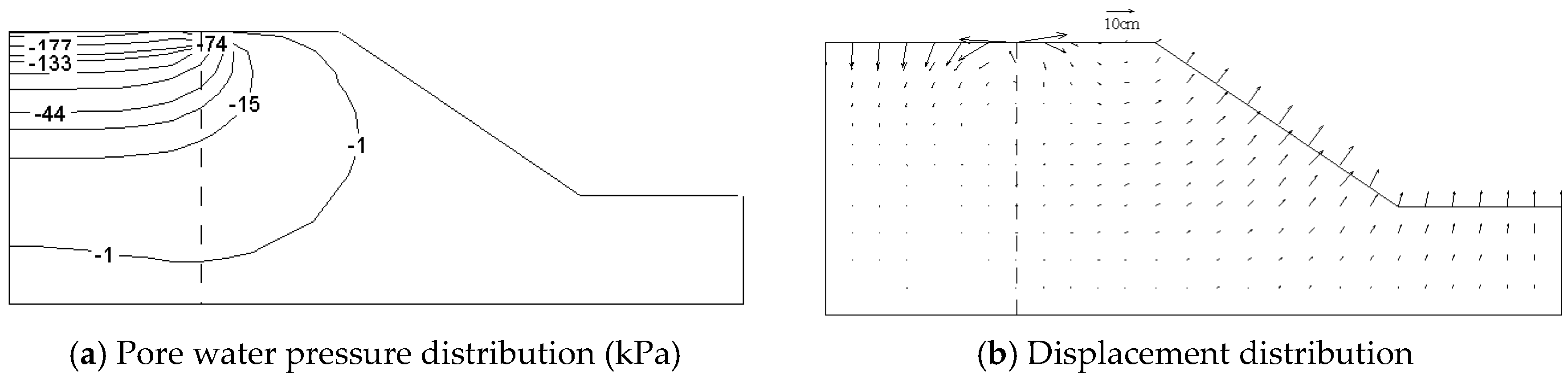
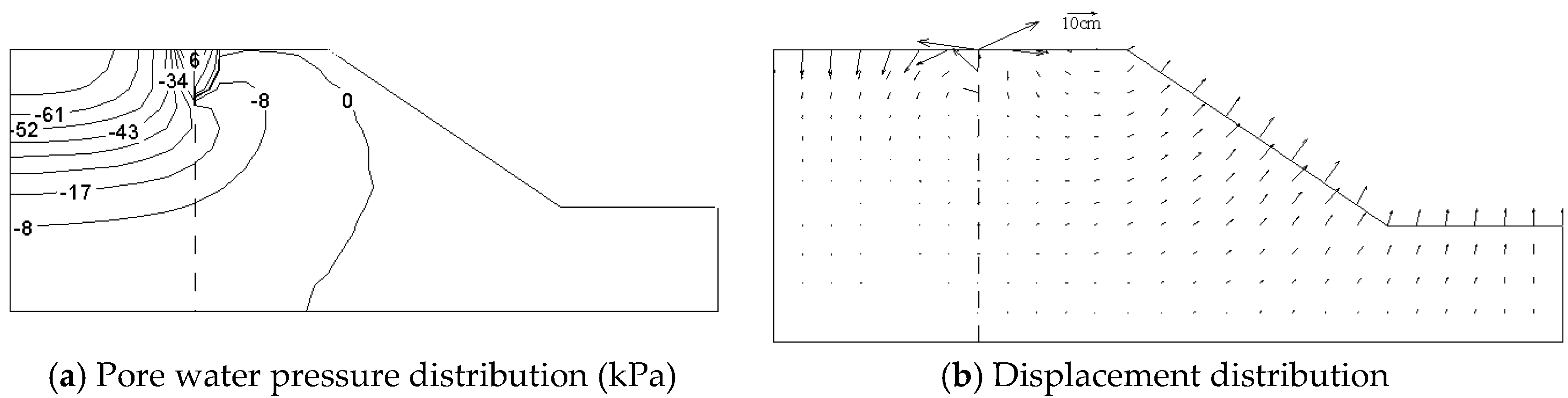
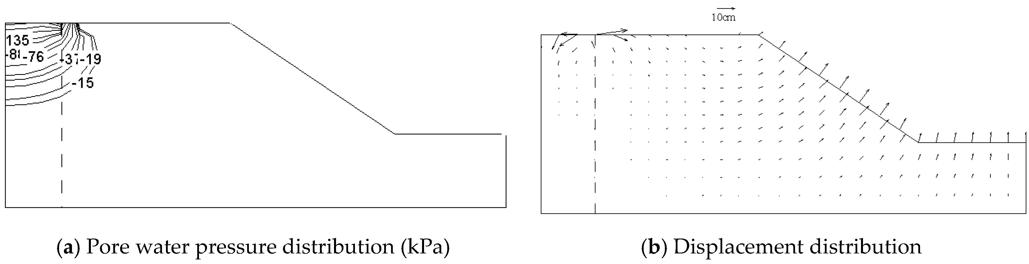
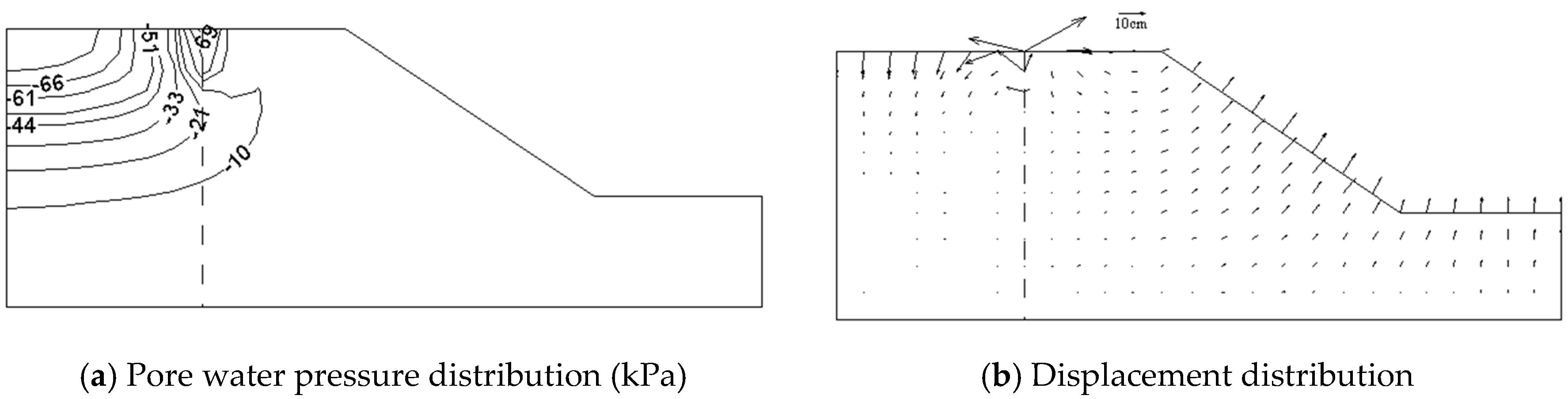
The pore water pressure distribution and displacement distribution at the end of evaporation of the baseline group were obtained as shown in Figure 4. The pore water pressure distribution and displacement distribution at the end of rainfall are shown in Figure 5.
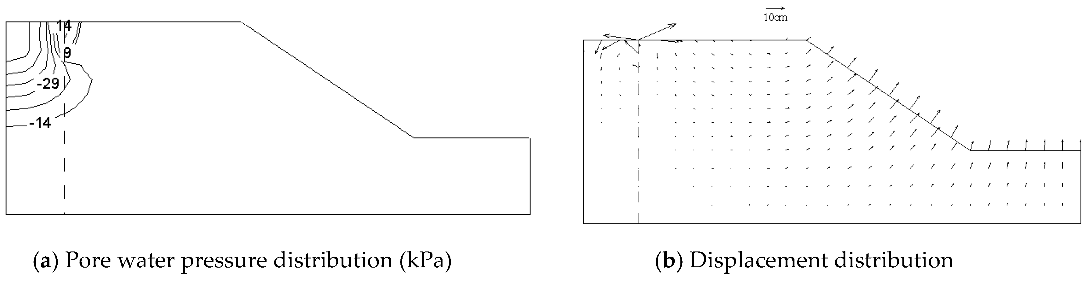
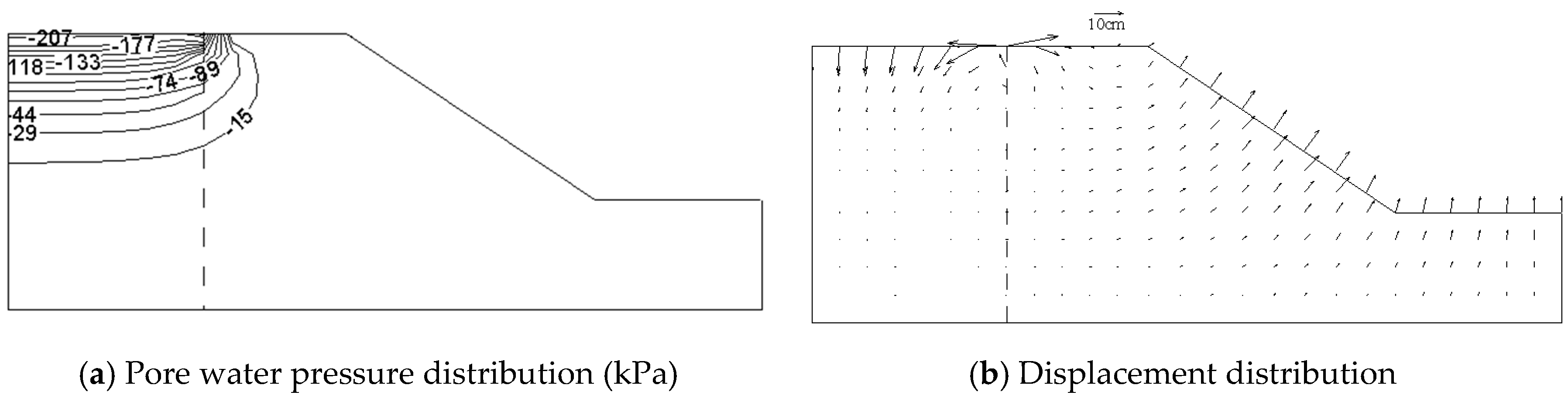
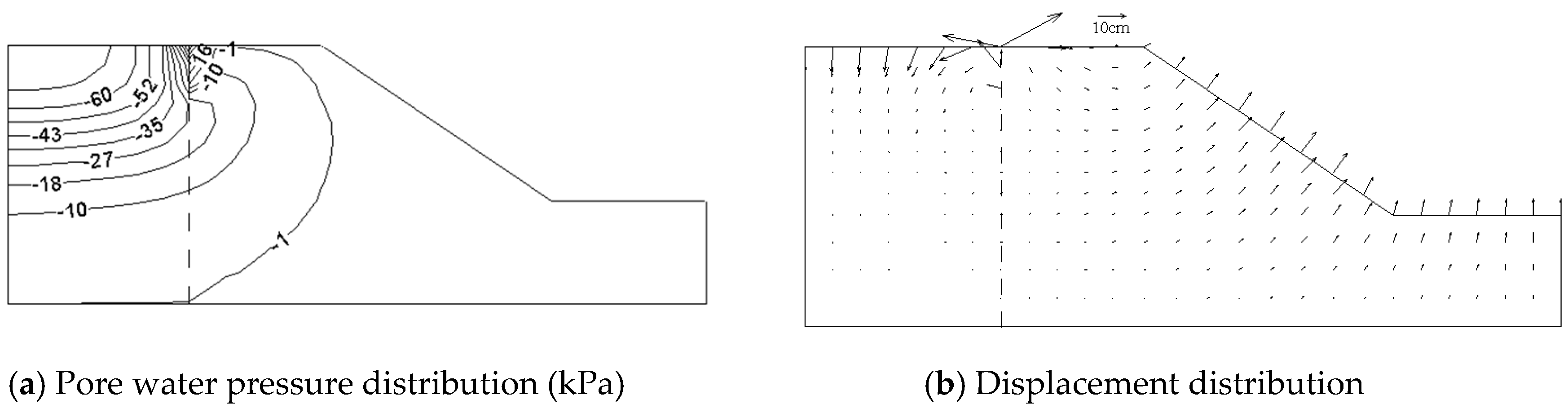
Figure 6 shows the pore water pressure distribution and displacement distribution at the end of evaporation when the crack was located 600 cm from the left edge of the soil slope. The pore water pressure distribution and displacement distribution at the end of rainfall are shown in Figure 7.
From the above figures, it can be seen that after the completion of evaporation, the appearance of the crack led to the discontinuity of pore water pressure distribution, the pore water pressure decreased, and then the pore water pressure rose significantly after the completion of rainfall and changed the most at the right side of the crack. It also caused the reduction of the influence on the right side of the slope. Then, the slopes with cracks at 1000 and 1800 cm from the left edge of the soil slope were analyzed as well. We found that the minimum pore water pressure of the soil slope decreased gradually and the crack width increased gradually as the crack location moved to the right side of the slope.
The curve of the crack width over time with cracks located at different locations is shown in Figure 8.
Figure 8 shows that the position of the crack had no influence on the development trend of the crack width. The cracks all appeared after 100 days of evaporation. When the evaporation developed, the crack developed quickly and then slowly. As for rain, the crack width slowly decreased and then slowly increased, and the maximum crack width appeared when the rainfall ended. Further, with the rightward movement of the crack, the crack width gradually increased, because the more the crack position was on the right slope, the closer the crack was to the slope surface, and the smaller the constraints were on the soil body.
3.2. Influence of Discharge Speed of Pore Air
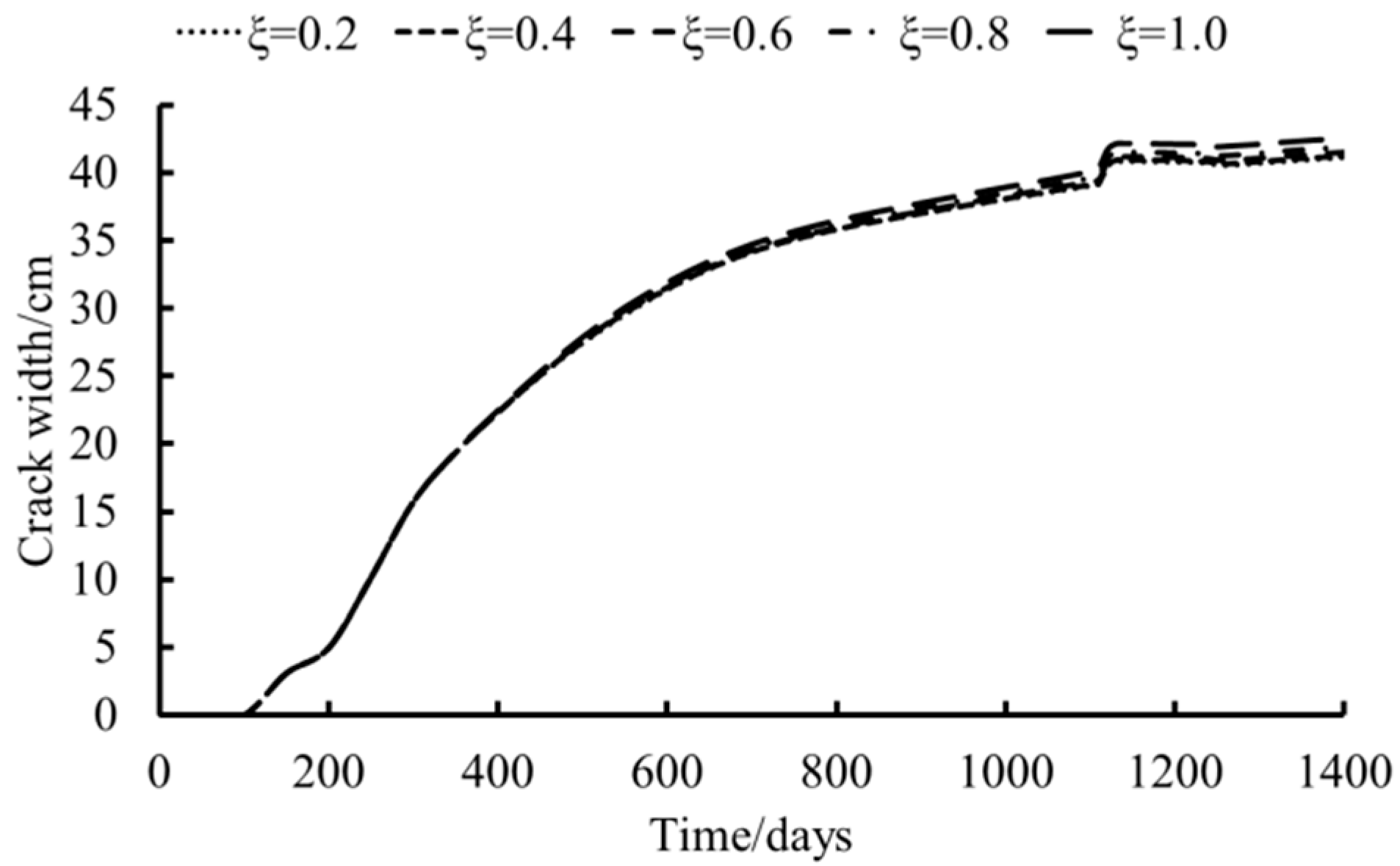
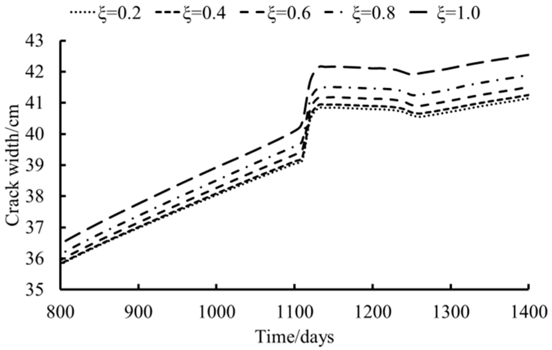
The numerical analysis of the unsaturated soil slopes with the discharge speeds of pore air of 0.2, 0.4, 0.8, and 1.0 respectively showed that there was not much difference between stress and deformation under each discharge speed, so they are not individually listed. Figure 9 shows the variation of crack width with time under different discharge speeds, and the crack-width–time curve under different discharge speeds after 800 days is shown in Figure 10.
As can be seen from Figure 9 and Figure 10, the greater the discharge speed, the greater the crack width, but the overall difference is not obvious. This is because the increase of the discharge speed caused the pore air to be expelled more quickly. The drier the soil was, the easier it was for the stress to reach the tensile strength, resulting in an increase in the crack width.
3.3. Influence of Evaporation Rate
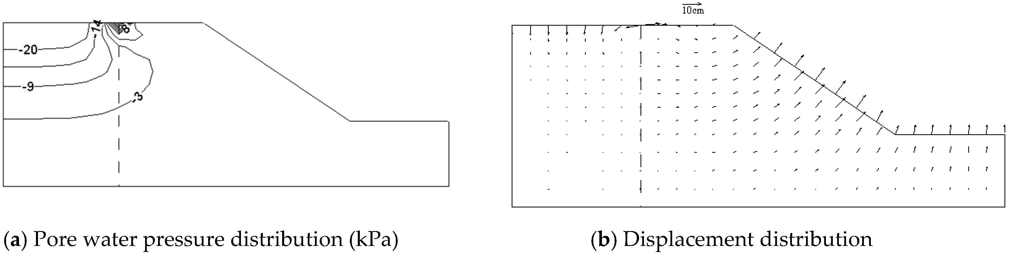
Figure 11 shows the pore water pressure and displacement distribution at the end of evaporation with an evaporation rate of 0.1 mm/day. Figure 12 shows the pore water pressure and displacement distribution at the end of rainfall with an evaporation rate of 0.1 mm/day.
Comparing Figure 11 and Figure 12 with Figure 4 and Figure 5, it is obvious that the negative pore water pressure increased as the evaporation rate changed from 0.3 to 0.1 mm/day, and the total displacement of the slope decreased.
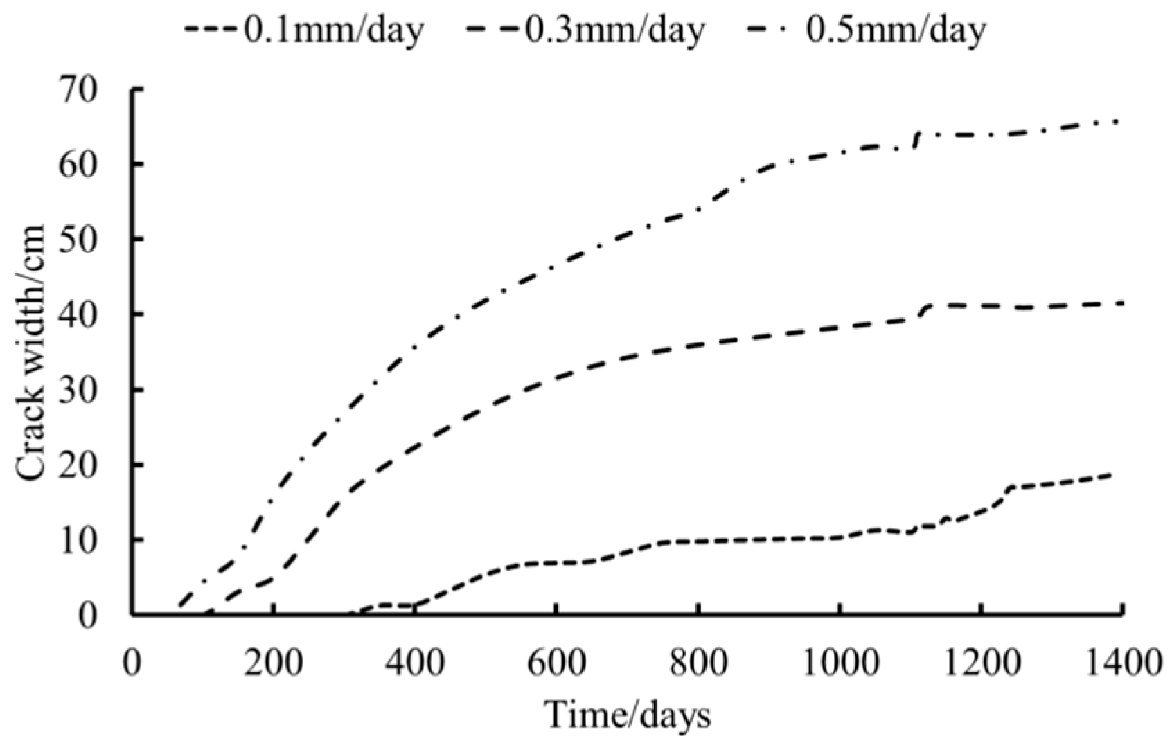
Then, we analyzed the condition of the evaporation rate being 0.5 mm/day. The variation of crack width with time under different evaporation rates is shown in Figure 13.
As can be seen in Figure 13, the greater the evaporation rate, the wider the crack, and the earlier the crack appeared. This is because when the evaporation rate was high, the pore water was reduced, so the negative pore water pressure decreased and the stress reached tensile stress quickly and finally made the crack width increase.
3.4. Influence of Infiltration Rate
For the numerical analysis of unsaturated soil slopes under different infiltration rate conditions, since the evaporation rate had not changed, the pore water pressure and the displacement distribution were the same as when the evaporation ended.
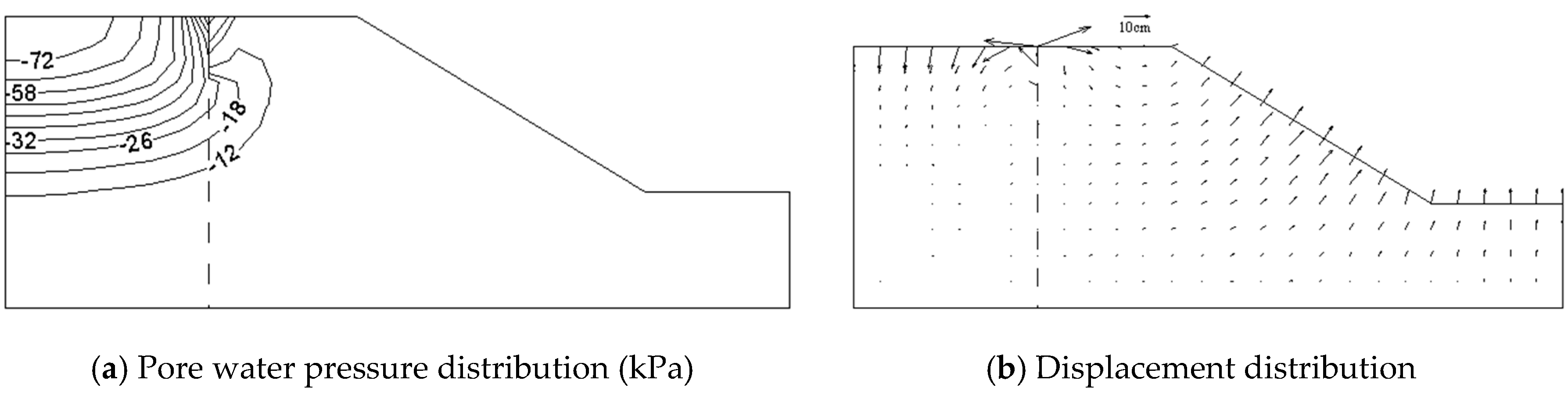
Figure 14 shows the pore water pressure distribution and displacement distribution at the end of rainfall with an infiltration rate of 0.1 mm/day.
Figure 15 shows the pore water pressure distribution and displacement distribution at the end of rainfall with an infiltration rate of 0.8 mm/day.
From the above figures, we can see that with the increase of the infiltration rate, the pore water pressure and displacement increased at the end of rainfall, and the change rules were similar.
The crack-width–time curve during the rainfall period is shown in Figure 16.
From Figure 16, we can see that the three lines show a decreasing trend at the initial phase but then increase till the end. As the infiltration rate increased, the crack width increased, the decreasing period became shorter, and the subsequent increasing rate increased. This is because at the beginning of the rain, the water infiltrated into the pore of the soils and slightly increased the tensile stress; but with the water infiltrating, the pore water stress increased, and a sustainable crack developed.
3.5. Influence of Tensile Strength
A numerical analysis was carried out on unsaturated soil slopes with tensile strengths of 1, 3, and 5 kPa (e.g., [42,43,44]).
Figure 17 shows the pore water pressure and displacement distributions at the end of evaporation under the condition of 1 kPa tensile strength, and Figure 18 shows the pore water pressure and displacement distributions at the end of rainfall under the condition of 1 kPa tensile strength.
Figure 17 and Figure 18 show that the larger the tensile strength, the smaller the pore water pressure. After the rainfall had completed, the pore water pressure around the crack increased greatly.
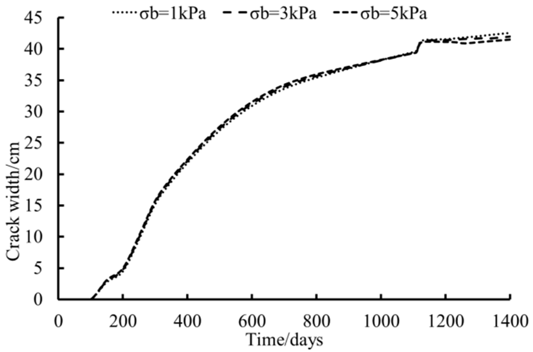
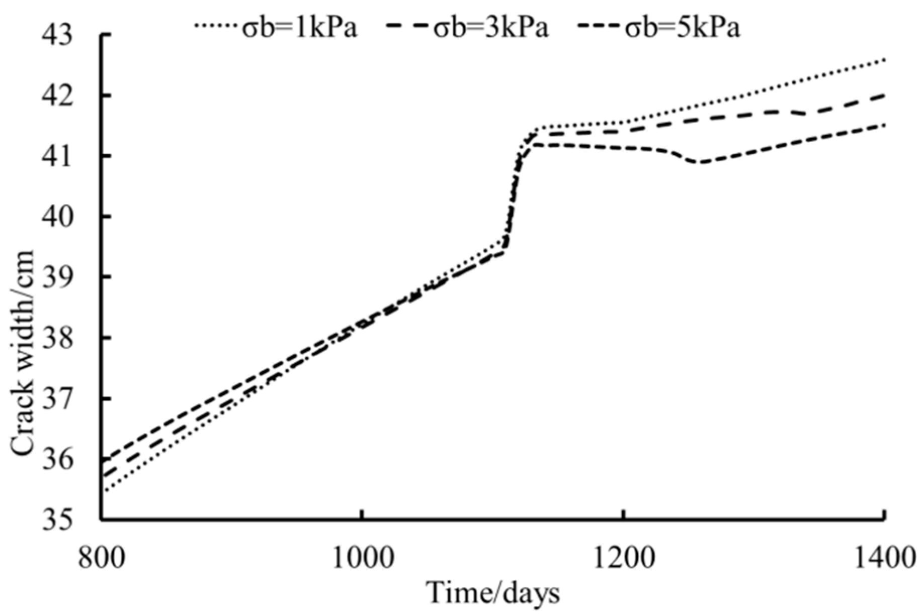
The crack-width–time curve under different tensile strength conditions is shown in Figure 19, and the crack-width–time curve under different tensile strength conditions after 800 days is shown in Figure 20.
From Figure 19 and Figure 20, we can see that when the evaporation developed, the crack width under 5 kPa of tensile stress was bigger than that under 3 kPa of tensile stress, and the crack width under 3 kPa was bigger than that under 1 kPa but almost the same. When it began raining, the crack width decreased as the tensile stress increased. This shows that increasing the tensile strength has a certain effect on reducing the crack width.
4. Conclusions
In this study, the finite element method was used to numerically analyze the development of cracks in unsaturated soil slopes, and the effect of crack characteristics on the stress and deformation of unsaturated soil slopes was studied. The main conclusions are as follows:
The finite element method considering the effective stress for unsaturated soil proposed by Bishop and an elastoplastic double-hardening constitutive model for the soil skeleton can be used to simulate the formation and propagation of cracks of unsaturated soil slopes.
The pore water pressure decreased and the crack width increased gradually with the right position of the crack. The larger the discharge speed, the greater the crack width. The negative pore water pressure increased as the evaporation rate increased, the total displacement of the slope decreased, and the crack widened and appeared earlier.
With the increase of the infiltration rate, the pore water pressure increased at the end of rainfall. The crack width at the rainfall stage firstly decreased and then increased, and as the infiltration rate increased, the decreasing stage became shorter and the crack width increased. The larger the tensile strength, the smaller the pore water pressure.
Author Contributions
Conceptualization, L.Y. and E.L.; methodology, L.Y. and E.L.; in-house codes, L.Y. and E.L.; validation, L.Y. and E.L.; formal analysis, L.Y.; investigation, L.Y. and E.L.; resources, E.L.; writing—original draft preparation, L.Y.; writing—review and editing, E.L. All authors have read and agreed to the published version of the manuscript.
Funding
This research was funded by the National Natural Science Foundation of China (NSFC) (Grant No. 41790431).
Acknowledgments
We thank the anonymous reviewers for their careful review, contributions, and critiques, which led to the improvement of the article, and everyone who offered to help with this article.
Conflicts of Interest
The authors declare no conflict of interest.
References
- Feng, S.Z.; Yan, P.W.; Cui, L. Instability mechanism of highway slope in arid areas and its stability analysis. Rock Soil Mech. 2009, 30, 144. [Google Scholar]
- Blatz, J.A.; Ferreira, N.J.; Graham, J. Effects of near-surface environmental conditions on instability of an unsaturated soil slope. Can. Geotech. J. 2004, 41, 1111–1126. [Google Scholar] [CrossRef]
- Rahardjo, H.; Lee, T.T.; Leong, E.C.; Razaur, R.B. Response of a residual soil slope to rainfall. Can. Geotech. J. 2005, 42, 340–351. [Google Scholar] [CrossRef]
- Timpong, S.; Itoh, K.; Toyosawa, Y. Geotechnical centrifuge modelling of slope failure induced by ground water table change. In Landslides and Climate Change; Taylor and Francis Group: London, UK, 2007; pp. 107–112. [Google Scholar]
- Ng, C.W.W.; Leung, A.K.; Yu, R.; Kamchoom, V. Hydrological effects of live poles on transient seepage in an unsaturated soil slope: Centrifuge and numerical study. J. Geotech. Geoenviron. Eng. 2016, 143, 4016106. [Google Scholar] [CrossRef] [Green Version]
- Jeong, S.; Lee, K.; Kim, J.; Kim, Y. Analysis of rainfall-induced landslide on unsaturated soil slopes. Sustainability 2017, 9, 1280. [Google Scholar] [CrossRef] [Green Version]
- Putra, H.; Rifa’I, A.; Sujono, J.; Silarukmi, A. Analysis of unsaturated soil parameters as slope stability mitigation. J. Teknol. 2017, 79, 21–27. [Google Scholar] [CrossRef] [Green Version]
- Ismail, M.A.M.; Hamzah, N.H. Study on the response of unsaturated soil slope based on the effects of rainfall intensity and slope angle. In Proceedings of the International Conference of Global Network for Innovative Technology, Penang, Malaysia, 27–29 January 2016; AIP Publishing LLC: New York, NY, USA, 2017; pp. 223–230. [Google Scholar]
- Sanavia, L.; Schrefler, B.A.; Steinmann, P. A formulation for an unsaturated porous medium undergoing large inelastic strains. Comput. Mech. 2002, 28, 137–151. [Google Scholar] [CrossRef]
- Khalili, N.; Habte, M.A.; Zargarbashi, S. A fully coupled flow deformation model for cyclic analysis of unsaturated soils including hydraulic and mechanical hystereses. Comput. Geotech. 2008, 35, 872–889. [Google Scholar] [CrossRef]
- Arson, C.; Gatmiri, B. Numerical study of a thermo-hydro-mechanical damage model for unsaturated porous media. Ann. Solid Struct. Mech. 2010, 1, 59–78. [Google Scholar] [CrossRef]
- Uzuoka, R.; Borja, R.I. Dynamics of unsaturated poroelastic solids at finite strain. Int. J. Numer. Anal. Methods Geomech. 2012, 36, 1535–1573. [Google Scholar] [CrossRef]
- Song, X.; Borja, R.I. Mathematical framework for unsaturated flow in the finite deformation range. Int. J. Numer. Methods Eng. 2014, 97, 658–682. [Google Scholar] [CrossRef]
- Shahbodagh-Khan, B.; Khalili, N.; Esgandani, G.A. A numerical model for nonlinear large deformation dynamic analysis of unsaturated porous media including hydraulic hysteresis. Comput. Geotech. 2015, 69, 411–423. [Google Scholar] [CrossRef]
- Oka, F.; Shahbodagh, B.; Kimoto, S. A computational model for dynamic strain localization in unsaturated elasto-viscoplastic soils. Int. J. Numer. Anal. Methods Geomech. 2018, 43, 138–165. [Google Scholar] [CrossRef] [Green Version]
- Ng, C.W.W.; Shi, Q. A numerical investigation of the stability of unsaturated soil slopes subjected to transient seepage. Comput. Geotech. 1998, 22, 1–28. [Google Scholar] [CrossRef]
- Gasmo, J.M.; Rahardjo, H.; Leong, E.C. Infiltration effects on stability of a residual soil slope. Comput. Geotech. 2000, 26, 145–165. [Google Scholar] [CrossRef]
- Cho, S.E.; Lee, S.R. Instability of unsaturated soil slopes due to infiltration. Comput. Geotech. 2001, 28, 185–208. [Google Scholar] [CrossRef]
- Shen, Z.J.; Mi, Z.K. Coupled analyses of seepage and deformation of expansive soil slopes during rainfall. Hydro Sci. Eng. 2004, 3, 7–11. [Google Scholar]
- Wang, H.L.; Xu, W.Y.; Tong, F.G. Coupled analysis of fracture rock mass slope saturated-unsaturated seepage field and stress field in flood discharge atomized rain area. Rock Soil Mech. 2008, 29, 2397–2403. [Google Scholar]
- Garcia, E.; Oka, F.; Kimoto, S. Numerical analysis of a one-dimensional infiltration problem in unsaturated soil by a seepage-deformation coupled method. Int. J. Numer. Anal. Methods Geomech. 2011, 35, 544–568. [Google Scholar] [CrossRef]
- Zhan, T.L.T.; Jia, G.W.; Chen, Y.M.; Fredlund, D.G.; Li, H. An analytical solution for rainfall infiltration into an unsaturated infinite slope and its application to slope stability analysis. Int. J. Numer. Anal. Methods Geomech. 2013, 37, 1737–1760. [Google Scholar] [CrossRef]
- Liu, E.L.; Yu, H.S.; Deng, G.; Zhang, J.H.; He, S.M. Numerical analysis of seepage-deformation in unsaturated soils. Acta Geotech. 2014, 9, 1045–1058. [Google Scholar] [CrossRef]
- Yeh, H.F.; Wang, J.; Shen, K.L.; Lee, C.H. Rainfall characteristics for anisotropic conductivity of unsaturated soil slopes. Environ. Earth Sci. 2015, 7, 93–108. [Google Scholar] [CrossRef]
- Arairo, W.; Prunier, F.; Djeran-Maigre, I.; Millard, A. Three-dimensional analysis of hydraulic effect on unsaturated slope stability. Environ. Geotech. 2015, 3. [Google Scholar] [CrossRef]
- Vahedifard, F.; Leshchinsky, D.; Mortezaei, K.; Lu, N. Effective stress-based limit-equilibrium analysis for homogeneous unsaturated slopes. Int. J. Geomech. 2016, 16, D4016003. [Google Scholar] [CrossRef]
- Kim, Y.; Jeong, S. Modeling of shallow landslides in an unsaturated soil slope using a coupled model. Geomech. Eng. 2017, 13, 353–370. [Google Scholar]
- Gofar, N.; Rahardjo, H. Saturated and unsaturated stability analysis of slope subjected to rainfall infiltration. Matec Web Conf. 2017, 101, 5004. [Google Scholar] [CrossRef] [Green Version]
- Arson, C.; Gatmiri, B. Numerical study of a new THM damage model for unsaturated geomaterials. In Proceedings of the 4th Asia-Pacific Conference on Unsaturated Soils, New-Castle, Australia, 23 November 2009. [Google Scholar]
- Zhou, C.; Cai, Z.Y.; Xie, H.P. Analytical model for the progressive deformation of natural fissured slopes. Chin. J. Geotech. Eng. 2006, 28, 174–178. [Google Scholar]
- Yuan, J.P.; Yin, Z.Z. Numerical model and simulation of expansive soils slope infiltration considered fissures. Rock Soil Mech. 2004, 10, 1581–1586. [Google Scholar]
- Ping, Y.; Liu, M.Z.; Zheng, S.H. Stability analysis of expansive soil slope with rainfall infiltration. Chin. J. Rock Mech. Eng. 2004, 23, 4478–4484. [Google Scholar]
- Chen, T.L.; Deng, G.; Chen, S.S.; Shen, Z.J. Effects of fissures on stability of unsaturated soil slope. Chin. J. Geotech. Eng. 2006, 28, 210–215. [Google Scholar]
- Liu, J.L.; Luan, M.T.; Wang, J.L.; Yuan, F.F. Seepage and stability analysis of saturated-unsautrated slope under rainfall infiltration. Rock Soil Mech. 2006, 27, 103–107. [Google Scholar]
- Sun, J.; Wang, G.; Sun, Q. Crack spacing of unsaturated soils in the critical state. Chin. Sci. Bull. 2009, 54, 2008–2012. [Google Scholar] [CrossRef] [Green Version]
- Li, J. Field Experimental Study and Numerical Simulation of Seepage in Saturated/Unsaturated Cracked Soil. Doctoral Dissertation, The Hong Kong University of Science and Technology, Hong Kong, 2009; pp. 278–291. [Google Scholar]
- Cao, L.; Wang, Z.; Chen, Y. Unsaturated Seepage Analysis of Cracked Soil including Development Process of Cracks. Adv. Mater. Sci. Eng. 2016, 2016, 2684297. [Google Scholar] [CrossRef] [Green Version]
- Shen, Z.J. Simplified consolidation theory for unsaturated soils and its application. Hydro Sci. Eng. 2003, 4, 1–6. [Google Scholar]
- Liu, E.L.; Xing, H.L. A double hardening thermo-mechanical constitutive model for overconsolidated clays. Acta Geotech. 2009, 4, 1. [Google Scholar] [CrossRef]
- Brooks, R.H.; Corey, A.T. Hydraulic Properties of Porous Medium; Hydrology Paper No. 3; Civil Engineering Department, Colorado State University: Fort Collins, CO, USA, 1964. [Google Scholar]
- Shen, Z.J.; Deng, G. Numerical simulation of crack formation process in clays during drying and wetting. Geomech. Geoengin. Int. J. 2006, 1, 27–41. [Google Scholar]
- Lo Presti, D.; Stacul, S.; Meisina, C.; Bordoni, M.; Bittelli, M. Preliminary validation of a novel method for the assessment of effective stress state in partially saturated soils by cone penetration tests. Geosciences 2018, 8, 30. [Google Scholar] [CrossRef] [Green Version]
- Vannucci, S.; Avanzi, G.D.; Galanti, Y.; Giannecchini, R.; Capilleri, P.P. Strength parameters of debris using a large shear box apparatus: Application to a case history. Rock Mech. Rock Eng. 2019, 52, 4421–4437. [Google Scholar] [CrossRef]
- Lo Presti, D.; Stacul, S.; Capilleri, P.P.; Squeglia, N. Assessment of Factors Contributing to Levees Stability. In Geotechnical Research for Land Protection and Development. CNRIG 2019. Lecture Notes in Civil Engineering; Calvetti, F., Cotecchia, F., Galli, A., Jommi, C., Eds.; Springer: Cham, Switzerland, 2020; Volume 40. [Google Scholar]
Figure 1.
Computational mesh and boundary conditions.

Figure 2.
The distributions of pore water pressure and displacement at the end of evaporation.

Figure 3.
The distributions of pore water pressure and displacement at the end of rainfall.

Figure 4.
The distributions of pore water pressure and displacement at the end of evaporation of baseline group.
Figure 4.
The distributions of pore water pressure and displacement at the end of evaporation of baseline group.

Figure 5.
The distributions of pore water pressure and displacement at the end of rainfall of baseline group.
Figure 5.
The distributions of pore water pressure and displacement at the end of rainfall of baseline group.

Figure 6.
The distributions of pore water pressure and displacement at the end of evaporation when the crack was located 600 cm from the left edge of the soil slope.
Figure 6.
The distributions of pore water pressure and displacement at the end of evaporation when the crack was located 600 cm from the left edge of the soil slope.

Figure 7.
The distributions of pore water pressure and displacement at the end of rainfall when the crack was located 600 cm from the left edge of the soil slope.
Figure 7.
The distributions of pore water pressure and displacement at the end of rainfall when the crack was located 600 cm from the left edge of the soil slope.

Figure 8.
Crack-width–time curve under different crack locations.

Figure 9.
Crack-width–time curve under different discharge speeds.

Figure 10.
Crack-width–time curve under different discharge speeds after 800 days.

Figure 11.
The distributions of pore water pressure and displacement at the end of evaporation with an evaporation rate of 0.1 mm/day.
Figure 11.
The distributions of pore water pressure and displacement at the end of evaporation with an evaporation rate of 0.1 mm/day.

Figure 12.
The distributions of pore water pressure and displacement at the end of rainfall with an evaporation rate of 0.1 mm/day.
Figure 12.
The distributions of pore water pressure and displacement at the end of rainfall with an evaporation rate of 0.1 mm/day.

Figure 13.
Crack-width–time curve under different evaporation rates.

Figure 14.
The distributions of pore water pressure and displacement at the end of rainfall with an infiltration rate of 0.1 mm/day.
Figure 14.
The distributions of pore water pressure and displacement at the end of rainfall with an infiltration rate of 0.1 mm/day.

Figure 15.
The distributions of pore water pressure and displacement at the end of rainfall with an infiltration rate of 0.8 mm/day.
Figure 15.
The distributions of pore water pressure and displacement at the end of rainfall with an infiltration rate of 0.8 mm/day.

Figure 16.
Crack-width–time curve with different infiltration rates during the rainfall period.

Figure 17.
The distributions of pore water pressure and displacement at the end of evaporation under the condition of 1 kPa tensile strength.
Figure 17.
The distributions of pore water pressure and displacement at the end of evaporation under the condition of 1 kPa tensile strength.

Figure 18.
The distributions of pore water pressure and displacement at the end of rainfall under the condition of 1 kPa tensile strength.
Figure 18.
The distributions of pore water pressure and displacement at the end of rainfall under the condition of 1 kPa tensile strength.

Figure 19.
Crack-width–time curve under different tensile strength conditions.

Figure 20.
Crack-width–time curve under different tensile strength conditions after 800 days.


Table 1.
Parameters changed in subsequent analysis.
| Name | Symbol | Unit |
|---|---|---|
| Crack location | \ | cm |
| Discharge speed of pore air | \ | |
| Evaporation rate | \ | mm/day |
| Infiltration rate | \ | mm/day |
| Tensile strength | kPa |
© 2020 by the authors. Licensee MDPI, Basel, Switzerland. This article is an open access article distributed under the terms and conditions of the Creative Commons Attribution (CC BY) license (http://creativecommons.org/licenses/by/4.0/).
Share and Cite
MDPI and ACS Style
Yang, L.; Liu, E. Numerical Analysis of the Effects of Crack Characteristics on the Stress and Deformation of Unsaturated Soil Slopes. Water 2020, 12, 194. https://doi.org/10.3390/w12010194
AMA Style
Yang L, Liu E. Numerical Analysis of the Effects of Crack Characteristics on the Stress and Deformation of Unsaturated Soil Slopes. Water. 2020; 12(1):194. https://doi.org/10.3390/w12010194
Chicago/Turabian StyleYang, Liuxin, and Enlong Liu. 2020. "Numerical Analysis of the Effects of Crack Characteristics on the Stress and Deformation of Unsaturated Soil Slopes" Water 12, no. 1: 194. https://doi.org/10.3390/w12010194
Note that from the first issue of 2016, this journal uses article numbers instead of page numbers. See further details here.