Humidification–Dehumidification (HDH) Desalination System with Air-Cooling Condenser and Cellulose Evaporative Pad


Mechanical Engineering Department, National Taiwan University, 708 Engineering Building, No.1 Section 4 Roosevelt Rd., Taipei 106, Taiwan
*
Author to whom correspondence should be addressed.
Water 2020, 12(1), 142; https://doi.org/10.3390/w12010142
Submission received: 27 October 2019
/
Revised: 23 December 2019
/
Accepted: 30 December 2019
/
Published: 2 January 2020
(This article belongs to the Section Wastewater Treatment and Reuse)
Abstract
:This paper presents a humidification–dehumidification (HDH) desalination system with an air-cooling condenser. Seawater in copper tubes is usually used in a condenser, but it has shown the drawbacks of pipe erosion, high cost of the copper material, etc. If air could be used as the cooling medium, it could not only avoid the above drawbacks but also allow much more flexible structure design of condensers, although the challenge is whether the air-cooing condenser can provide as much cooling capability as water cooling condensers. There is no previous work that uses air as cooling medium in a condenser of a HDH desalination system to the best of our knowledge. In this paper we designed a unique air-cooling condenser that was composed of closely packed hollow polycarbonate (PC) boards. The structure was designed to create large surface area of 13.5 m2 with the volume of only 0.1 m3. The 0.2 mm thin thickness of the material helped to reduce the thermal resistance between the warm humid air and cooling air. A fan was used to suck the ambient air in and out of the condenser as an open system to the environment. Results show that the air-cooling condenser could provide high cooling capability to produce fresh water efficiently. Meanwhile, cellulous pad material was used in the humidifier to enhance the evaporative process. A maximum productivity of 129 kg/day was achieved using the humidifier with a 0.0525 m3 cellulous pad with a water temperature of 49.5 °C. The maximum gained output ratio (GOR) was 0.53, and the maximum coefficient of performance (COP) was 20.7 for waste heat recovery. It was found that the system performance was compromised as the ambient temperature increased due to the increased temperature of cooling air; however, such an effect could be compensated by increasing the volume of the condenser.
1. Introduction
Fresh water is very important for human life regarding development in industry, agriculture and livelihood. The scarcity of fresh water in some countries and areas has driven the research and development in desalination in recent decades. Various types of technology have been developed for desalination, such as multi-stage flash (MSF), multi-effect desalination (MED), reverse osmosis (RO), and humidification and de-humidification (HDH) [1]. Some of these technologies have been commercialized at large scales; however, there are the drawbacks such as high capital cost and high operation cost [2]. HDH systems are advantageous in many ways, such as flexible scales, simple layout, low temperature operation, low capital cost and operation cost, and could be combined with renewable energy resources such as solar energy [3,4].
Many research groups have presented their design and results of HDH desalination systems in recent decades. The performance of these system depends on fluid properties and conditions, including flow rate and temperature, and also relate to the configuration and materials of either humidifier or dehumidifier. W.F. He et al. [5] presented the analysis of an open-air open-water HDH system with a packing bed dehumidifier. Results showed that higher humidifier and dehumidifier effectiveness can benefit the thermodynamic performance and production cost. Ahmed et al. [6] proposed an analytical and numerical scheme for thermodynamically balanced HDH systems. Ghazi et al. [7] evaluated the characteristics of the HDH desalination process as a function of operating conditions such as air flow rate and cooling water temperature. They reported a water production increase upon the increase in the air flow rate and decrease in the cooling water temperature. Zehui Chang et al. [8] presented a novel multi-effect solar desalination system based on HDH and used a porous balls humidifier to increase the contact surface area. They showed that the multi-effect solar HDH desalination system could be potentially improved through the optimization of its design and operation. Abdelrahman et al. [9] assessed a cross-flow HDH system experimentally. They found that the productivity greatly depended on either the hot water temperature or the water flow rate, and there existed an optimal condition for the performance of their system in different cases. Hossam A. Ahmed et al. [10] presented an experimental study with packed aluminum sheets as the material in the humidifier, and showed results such as humidify efficiency, enthalpy effectiveness and performance coefficient. They found that the air temperature at the humidifier inlet has a smaller effect on productivity compared to the hot water temperature. A.E. Kabeel et al. [11] combined the HDH desalination system and a solar dryer. The latter provided additional vapor to the HDH system while drying food. E.H. Amer et al. [12] obtained experimental and theoretical results in different materials of humidifier. Their mathematical model was formulated by applying mass and energy balance on a control-volume to find the maximal productivity among different packing materials. G. Prakash Narayan et al. [13] presented the simulation results for different types of HDH system, such as CWOA (closed-water, open-air) HDH, CAOW (closed-air, open-water) HDH and others. They used the second law of thermodynamics to analyze the optimal conditions of each system. G. Prakash Narayan et al. [14] also presented analysis to obtain the optimization of effectiveness and other measures. Dahiru Lawal et al. [15] presented simulation results by adopting a heat pump in a HDH system. Their results showed that the performance of the HDH system could be significantly increased by using a heat pump. W.F. He et al. [16] also studied a HDH system with a heat pump. The simulation results showed that the best performance as 82.12 kg/h for the water production and 5.14 for the GOR.
The cooling medium in the dehumidifier in these studies was usually sea water. Sea water in heat exchangers can cause problems, such as the erosion of parts from the high salt content and pipe blocking from impurities in the sea water. Copper material is usually used for the cooling system, which increases the cost of the system. Therefore, there is high motivation to use an alternative cooling medium that can also provide a sufficient cooling capability. In this paper we proposed a unique air-cooling condenser design that can efficiently cool down the warm humid air and produce the fresh water efficiently.
Using air as the cooling medium in the condenser of a HDH system is challenging and no previous work has been reported to the authors’ knowledge. Air has a much lower mass density, lower heater capacity and lower thermal conductivity than water. Several means have been applied in the design to enhance the heat transfer rate, including maximizing the surface area of heat transfer, using thin thickness of material to reduce thermal resistance between the cooling air and the warm humid air, etc. The condenser is an open system to the environment and a fan was used to suck the ambient air into the condenser and the heated air to the ambient without using any pipes. The flow rate of the cooling air can be increased independently to increase the heat transfer rate. There was no copper material or any other metal materials in the condenser, and therefore the total system cost was reduced.
Another feature of our system is the use of a cellulose pad as the filling material in the humidifier. Most conventional humidifiers use plastics as the filling material. The surface of plastic material is usually hydrophobic, which means the wettability of the water on the plastic surface is poor. Water forms streams instead of films on the plastic surface, and thus the contact area between the air and water is much less than the surface area of the plastic fillings. Therefore, a cellulose pad is used as an alternative filling material in the humidifier. The cellulose pad is designed as a cellulose-bound cardboard structure and of a cross-fluted type. The capillary force results in the strong absorption of water into the cellulose pad, which makes the cellulose pad a water dispersing device once saturated. Such design greatly increases the contact area between air and water and can generate vapor very efficiently [17,18].
2. Experiment Setup
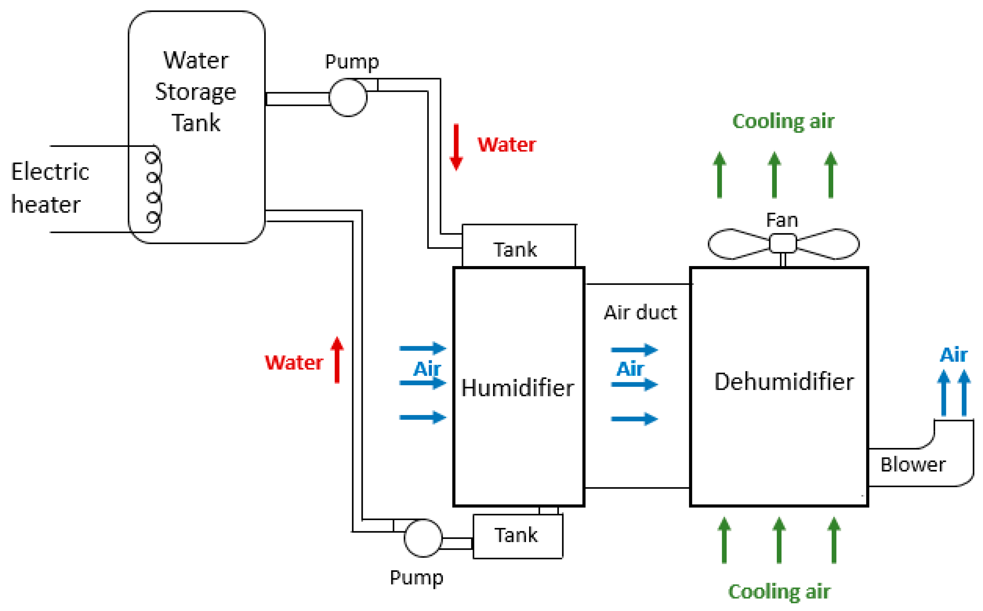
Our humidifier–dehumidifier (HDH) system was a closed-water-open-air (CWOA) system and the schematic diagram of the experiment setup is shown in Figure 1. The storage tank contained hot water that was heated by an electric heater. Hot water was pumped into a tank on top of the humidifier and a big chuck of sponge was placed at the exit of the tank to help evenly distribute hot water throughout the humidifier. The humidifier contained a cellulose pad with a large surface area in direct contact with the hot water, which generated vapor efficiently. The rejected water was collected at the bottom tank and cycled back to the storage tank by another pump.
The hot humid air was carried to the dehumidifier through an air duct under the drive of the blower located at the dehumidifier side. Cooling air from the ambient was driven by a fan located at the top of the dehumidifier and the flow direction was from the bottom to the top of the dehumidifier. The dehumidifier was composed of closely packed hollow polycarbonate (PC) boards that allowed humid air to flow between the PC boards while allowing the cooling air to flow inside the channels of hollow PC boards in a cross direction. The vapor in the humid air condensed on the walls of the PC boards and was collected by the container underneath the dehumidifier. After passing the dehumidifier, the cooled humid air flew out of the system as an exhaust.
A detailed description of the experimental setup is as follows. Three electric heaters with 2 kW each were used to heat the water in the storage tank. A control system was employed to keep the water temperature constant at the experiment conditions and kept the amount of water in the storage tank constant with feed-in water. The hot water temperature was limited to 50 °C, as the expected temperature of heated water by the photovoltaic thermal (PVT) collector was about in this range. The power of the two pumps that cycled the hot water were 50 W and 70 W, respectively.
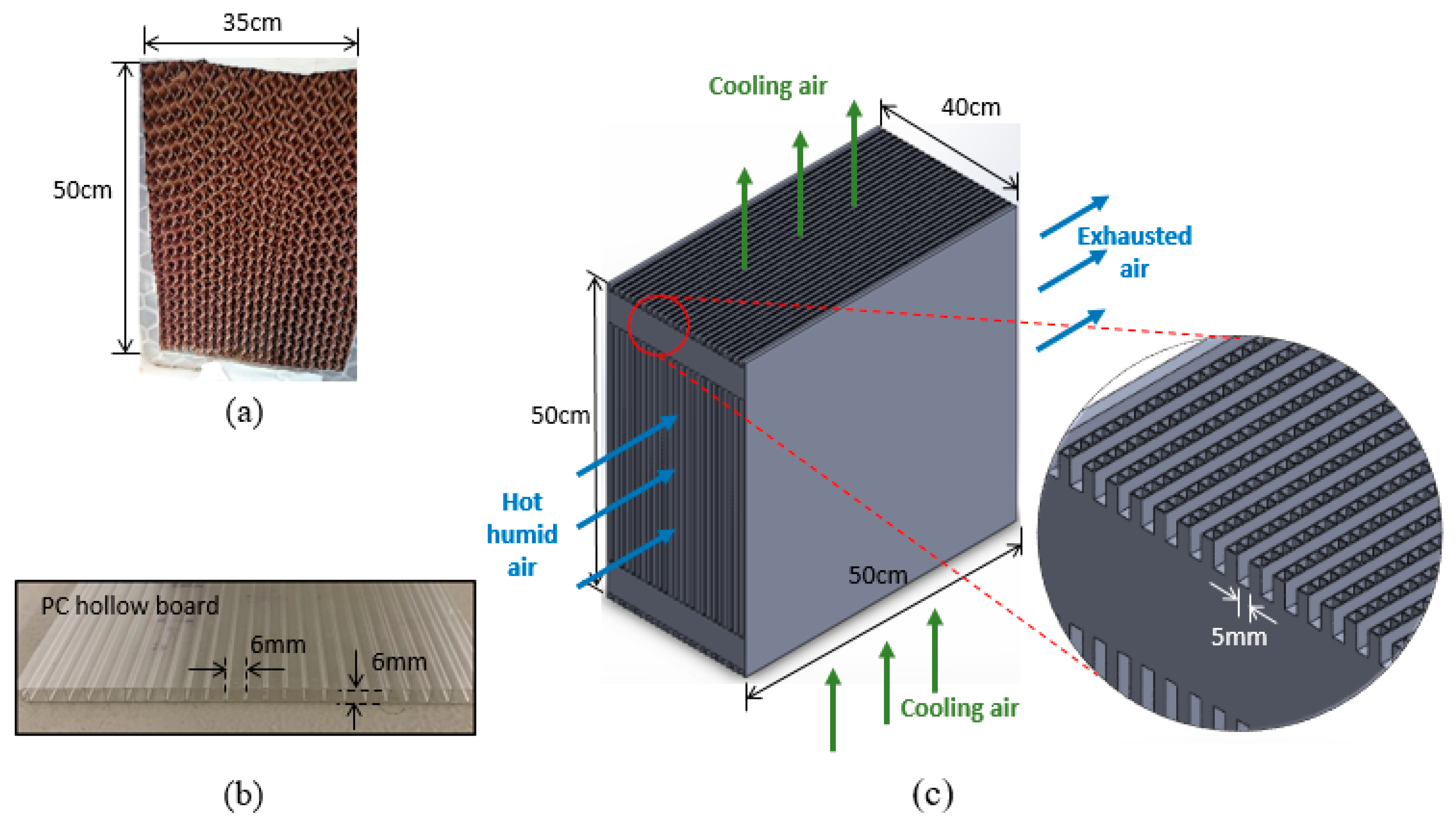
The size of the cellulose pad in the humidifier, as shown in Figure 2a, was 50 cm in height, 35 cm in width and 30 cm in length, with a volume of 0.0525 m3. The size of the condenser made of hollow polycarbonate (PC) boards in the dehumidifier was about 50 cm in height, 40 cm in width and 50 cm in length, with a volume of 0.1 m3. The hollow PC boards contains channels with a cross section of 6 mm × 6 mm, as shown in Figure 2b. Twenty-eight pieces of PC board were assembled in parallel with an even spacing of 5 mm by fixture and epoxy, as shown in Figure 2c. The total surface contact area was about 13.5 m2. The system was designed such that the hot humid air flowed between the PC boards, while the cooling air flowed through the channels inside the PC boards in the cross direction, without direct contact between the two fluids.
The temperature and humidity were measured by a T-type thermocouple and psychrometer at multiple points across the section of the air duct and at the exit of the dehumidifier. The air velocity was measured by an anemometer. The flow rate of the water was measured by a measuring cup.
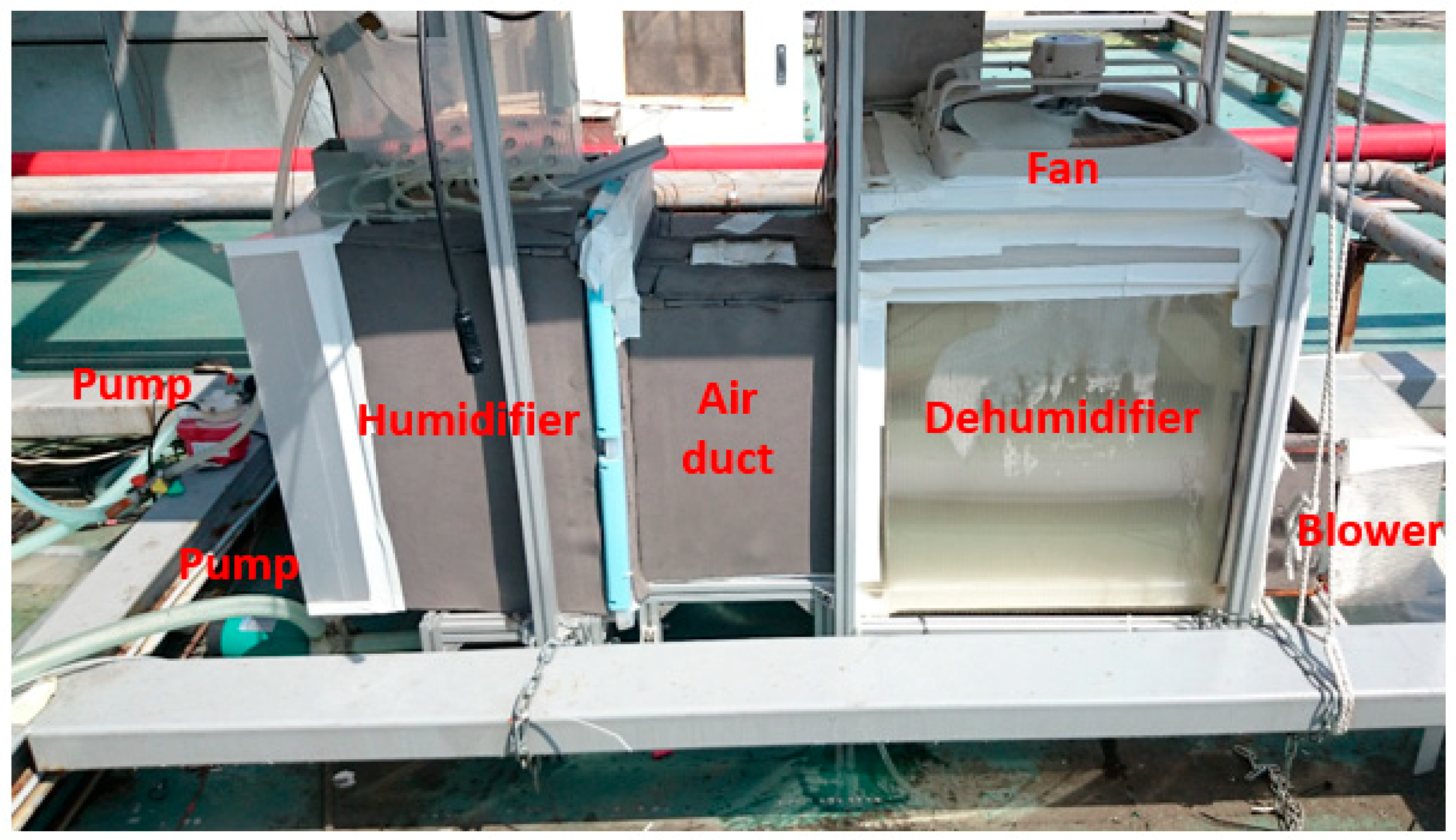
A photograph of the actual system was shown in Figure 3.
3. Thermodynamic Analysis
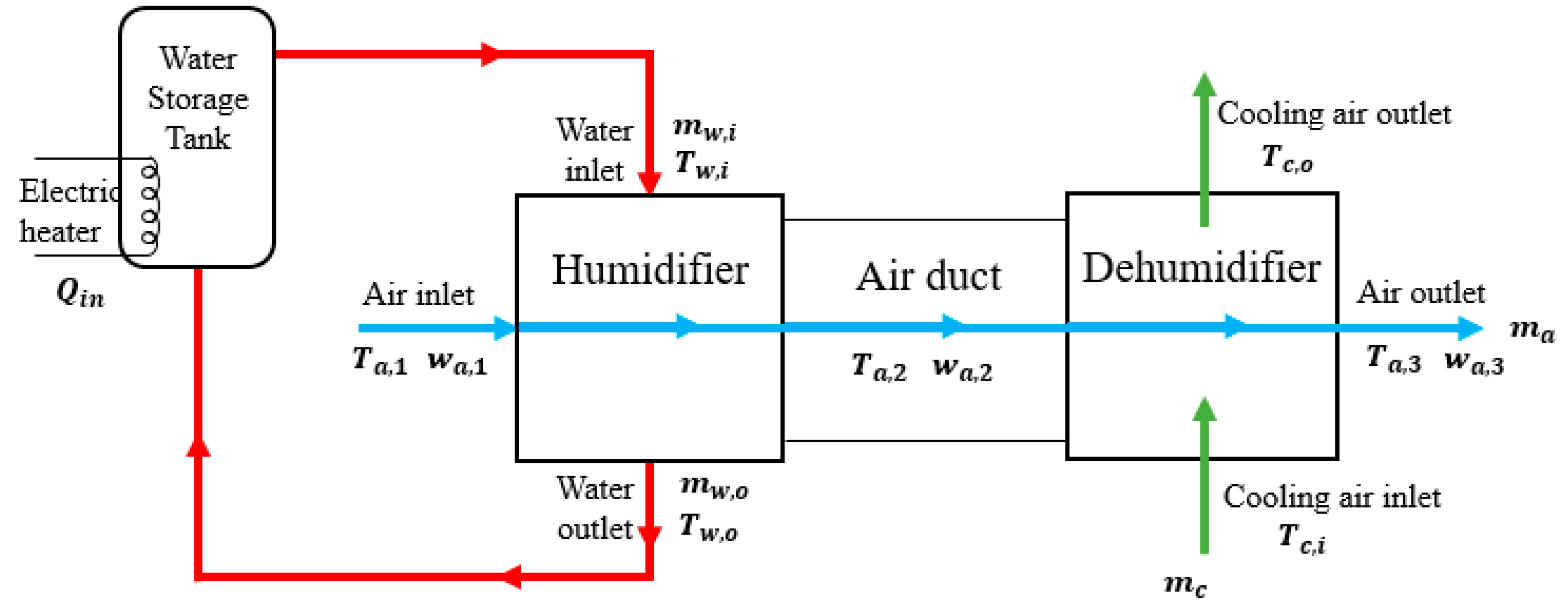
Several parameters were used to evaluate the performance of our HDH desalination system. The applied principles of thermodynamics are mass and energy conservation and the entropy increase in each process. A diagram for thermodynamic analysis was shown in Figure 4.
The mass ratio (MR) is a ratio between the hot water mass rate and the air mass rate as follows:
where is the mass rate of air and is the mass rate of water in the humidifier inlet.
The gained output ratio (GOR) is commonly used to evaluate the performance of a HDH system. It is defined as the ratio of the latent heat of generated fresh water over the input heat (while the work input of pumps and fans is negligible) as follows
where is the mass rate of produced water in dehumidification, is latent heat of water and is heat input of this system. is evaluated with the energy balance of the water storage tank as
where and are the hot water mass flow rate at the inlet and outlet of humidifier, respectively, and and are the enthalpy of the hot water at the inlet and outlet of the humidifier, respectively, is the evaporation rate in humidifier which equals to the feed water rate at steady state condition, and is the enthalpy of the feed water at ambient temperature.
The recovery ratio (RR) is a ratio of the mass rate of condensed water in the dehumidifier over the mass rate of evaporated water. RR is defined as
where is the mass rate of evaporated water in the humidifier and calculated by mass conservation as
where is the absolute humidity at the inlet of the humidifier and is the absolute humidity at the outlet of the humidifier.
The coefficient of performance (COP) is a coefficient to obtain performance of a system, typically used in cooling systems such as heat pumps. It is defined as
where is the total power consumption of this system, excluding .
To evaluate the performance of our system, we defined the effectiveness of the HDH system. The commonly used effectiveness is diverse in the simultaneous heat and mass exchanger or heat exchanger. We considered that the performance of HDH greatly depends on the fluid property described as enthalpy, so the definition of effectiveness for HDH is as [14]:
where ΔH is the actual enthalpy change of either water steam or air stream, and ΔHmax is the maximum possible enthalpy change.
The above Equation is based on mass and energy conservation, so the effectiveness is the ratio of real enthalpy change over maximum possible enthalpy change, which could be achieved in either stream. We name the enthalpy of any stream(x) in ideal state . Thus, the humidifier effectiveness ( could be defined as the following [13]:
The max symbol is to make sure that the definition is not against the second law of thermodynamics. Similarly, the dehumidifier effectiveness ( could be defined as
where the temperature of is assumed to be and is calculated when the air temperature at the dehumidifier outlet () is set to be the ambient temperature.
4. Results and Discussion
Table 1 lists some selected previous work with similar configuration of HDH systems to compare with ours. The hot water temperature in our system is set at 40 to 50 °C to simulate hot water from a photovoltaic thermal (PVT) collector. Taking into account the size difference of the lab systems, a calculation was done by setting the feed water flow rate to be the same and modifying the productivity proportionally. At the temperature range of 40–50 °C results showed that the productivity of our system was the highest among the listed previous work in Table 1.
4.1. Part 1. Effect of Mass Ratio
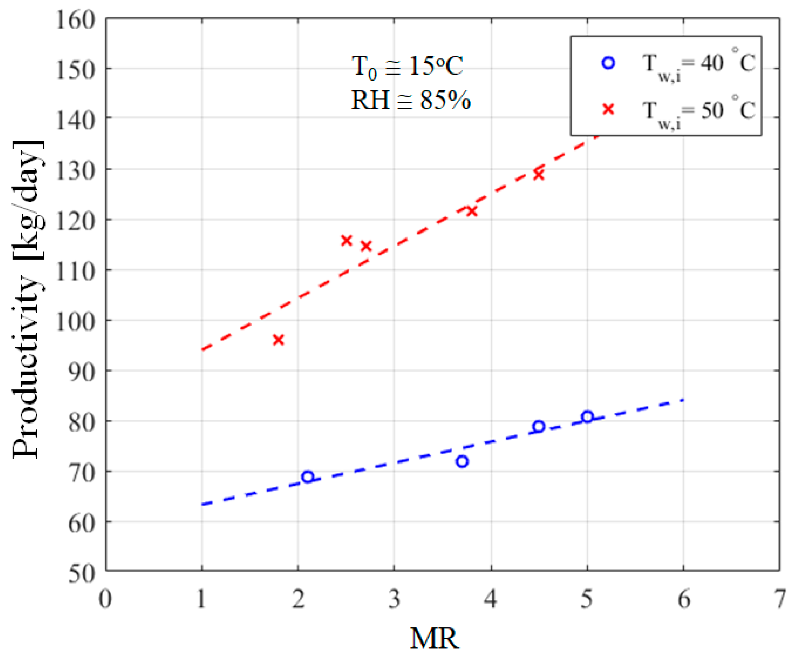
The amount of fresh water produced per day, or productivity, is an important measure of a HDH desalination system. The correlation between productivity and the mass ratio of hot water and air (MR) is shown in Figure 5. Productivity, measured by the produced fresh water, increased as MR increased, which was attributed to the increasing amount of vapor carried by the air at higher water flow rates. As the water flow rate increased, the contact area between the hot water and the cellulose pad increased, since a larger volume of the cellulose pad was soaked. It is also shown in Figure 5 that a higher water temperature improved the productivity, as the evaporation rate increased at higher water temperatures. The increase in productivity was more significant at higher water temperatures, as indicated by the slope of the trend lines.
Table 2 lists the experiment data for some example runs.
The measured average temperature at the outlet of the humidifier Ta,2 increased as MR increased, as shown in the left y-axis of Figure 6. The absolute humidity wa,2 in the air duct, as shown in the right y-axis of Figure 6, represented the amount of the vapor generated by the humidifier. It was expressed as vapor mass over air mass and was calculated from the measured temperature and relative humidity across the air duct at the outlet of the humidifier. The results in Figure 6 show a positive correlation between the generated vapor and the mass ratio, i.e., the higher the mass ratio, the higher the temperature and the absolute humidity at the exit of the humidifier.
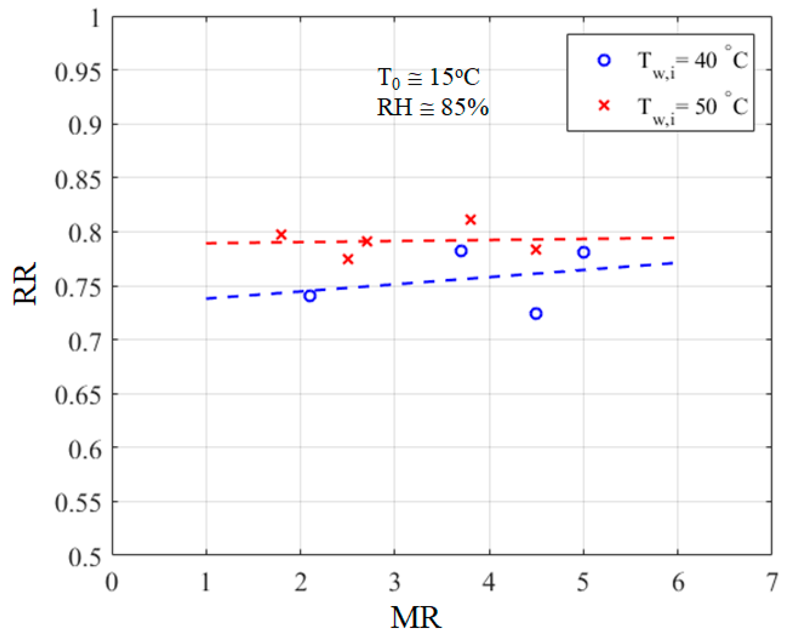
The gained output ratio (GOR), as an important measure of HDH system performance, varied with the mass ratio, as shown in Figure 7. A higher mass ratio resulted in a higher GOR. A higher water temperature also improved GOR. The results show that the recovery ratio (RR) was relatively constant as MR varied, as shown in Figure 8. In other words, the capability to transform the vapor into water in the condenser was constant. The same portion of the vapor could be extracted in the humidifier, in spite of the amount of vapor carried by the air. This was probably attributed to the high cooling capability of the condenser, and it was evidenced by the constant dehumidifier effectiveness which will be discussed in a later section.
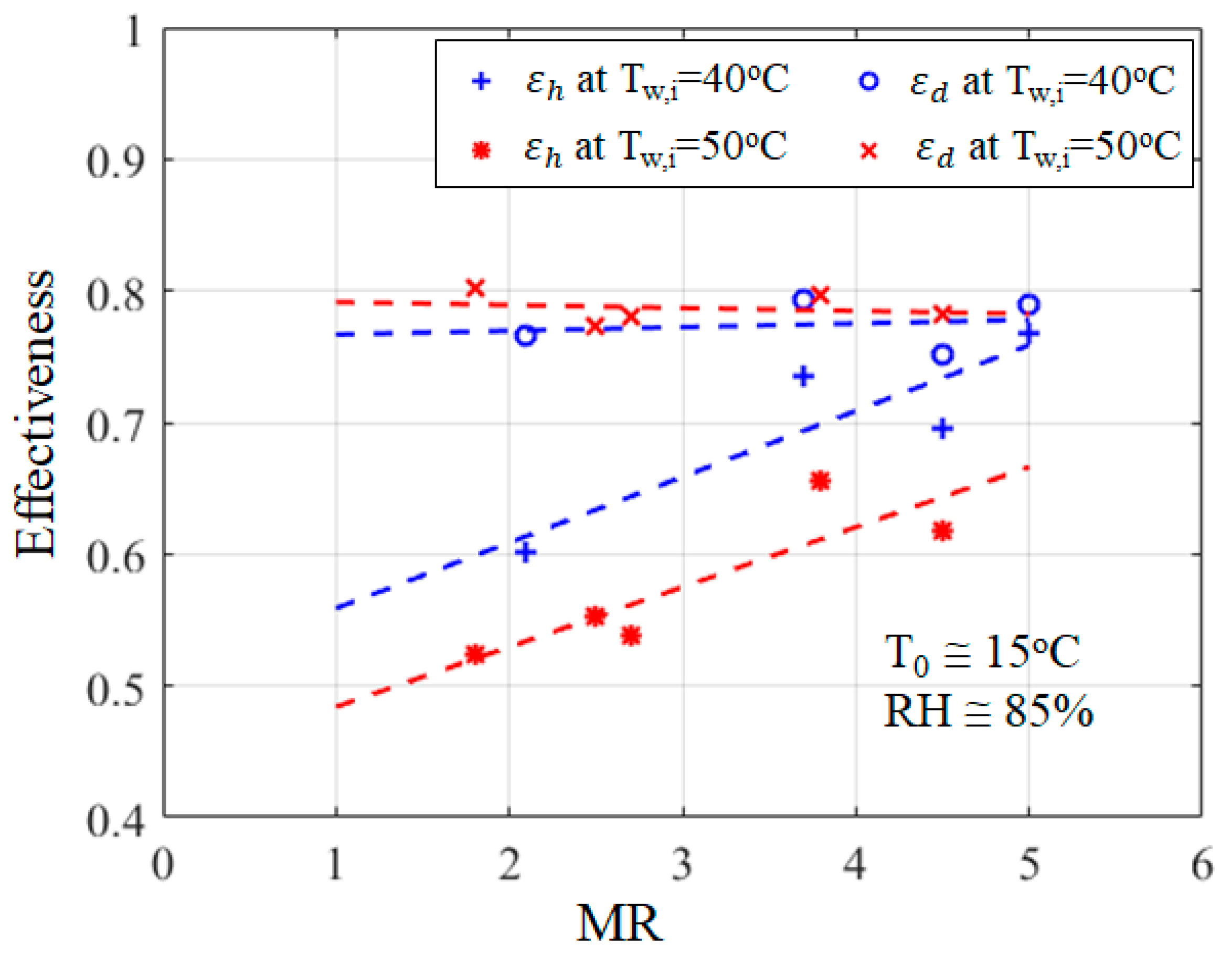
The humidifier effectiveness and dehumidifier effectiveness , as defined in Equations (8) and (9), varied with MR as shown in Figure 9. The humidifier effectiveness was positively correlated with MR. A higher mass rate of hot water resulted in a larger contact area, which raised the air temperature and the absolute humidity as the hot water mixed with the incoming air in the humidifier. The dehumidifier effectiveness did not show much change with MR. The reason was probably because the cooling capability of the condenser was sufficient to condense the vapor under all the experiment conditions. This may be attributed to the efficient heat exchange between the hot humid air and the cooling air in the unique design of the condenser.
One of the reasons we think that the air-cooling condenser could work is that the ambient air as the cooling medium has no energy cost and the system can take as much air as it needs to cool down the warm humid air, while a water-cooling condenser needs to match the flow rate of water in the condenser with that in the humidifier, and limits how fast the cooling water (or preheated water) could flow. In other words water-cooling condensers recycle the heat, but compromise on the cooling capability of the condenser. The air-cooling condenser worked more independently, and it could condense the water vapor efficiently with a large surface area.
4.2. Part 2. Effect of Power Consumption on COP
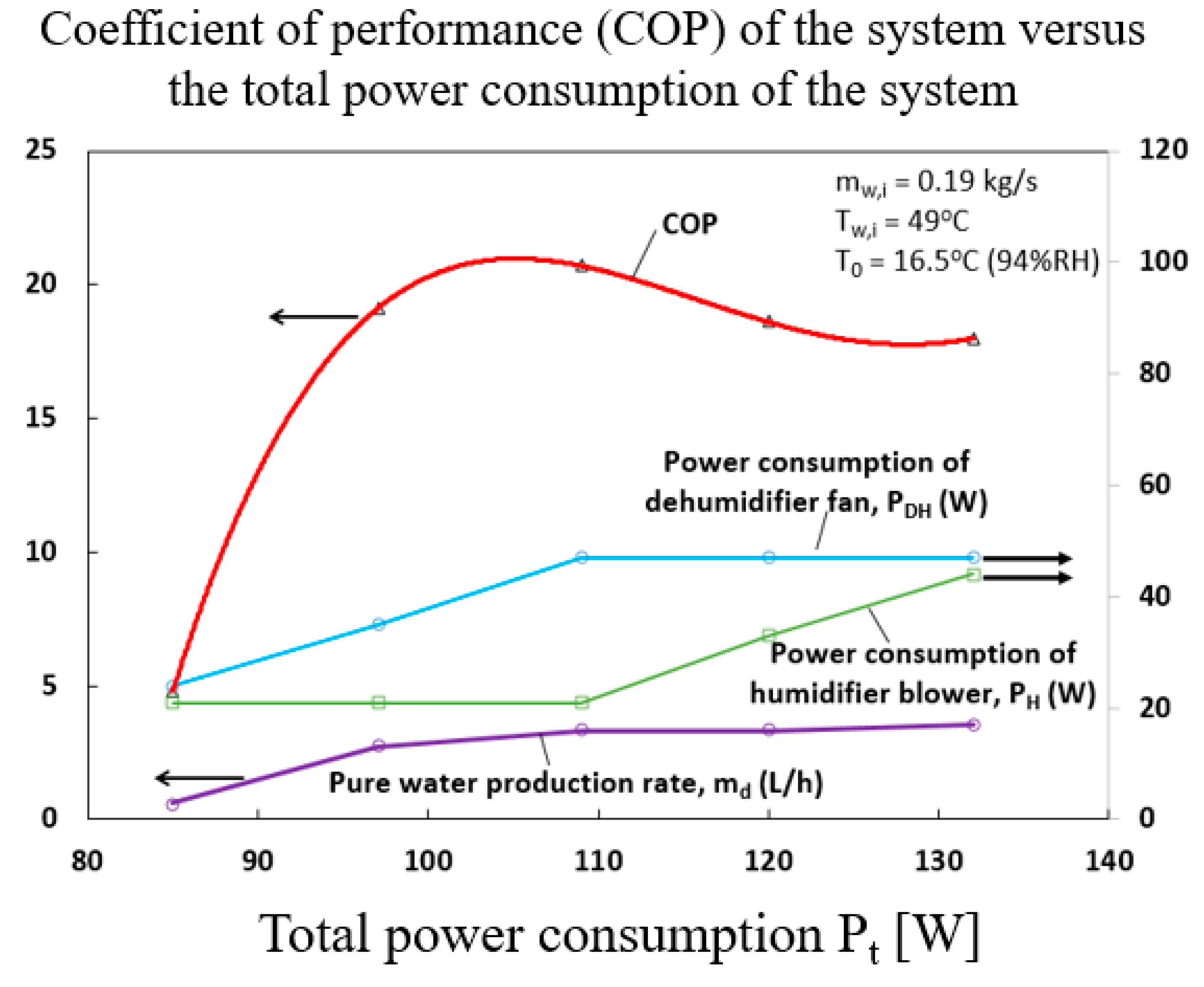
The coefficient of performance (COP) is an important measure to evaluate how much useful thermal energy we can obtain provided the amount of work required. In our case, it was calculated as the ratio of the latent heat of fresh water over the work of the whole system, including pumps, fans etc., but excluding for the application of waste heat recovery. The maximal COP of 20.7 has been achieved with our system. The correlation between the COP and the total power consumption (Pt) is shown in Figure 10. The power consumption of the humidifier fan (PH) and dehumidifier fan (PDH) varied to find the maximum COP, while the power consumption of the rest of the system (pumps) was kept constant. The humidifier fan was the blower that delivered the vapor-carrying air through the system and the dehumidifier fan was the fan that delivered the cooling air into the dehumidifier. The left half of Figure 10 shows that the COP was positively correlated to PDH when PH was kept constant. This was probably because the higher PDH resulted in a higher cooling capability of the dehumidifier and increased the pure water production rate significantly. The right half of Figure 10 shows that the COP was negatively correlative with PH when PDH was kept constant. The reason was probably that a larger PH did not increase the fresh water production much, but the total power consumption increased, resulting a lower COP. The data of some experimental runs are presented in Table 3.
Another measure of the system performance is the performance ratio (PR), recently developed using an exergy approach by Ng, K.C., et al. [22]. The calculated result of PR for our system is about 9.8, based on the Equation given in the article.
4.3. Part 3. Effect of Ambient Temperature
We did experiments at different ambient temperatures and found that the ambient temperature influenced the system performance in two main aspects. One was the carrying air temperature and the other was the cooling air temperature. The two effects influenced the system performance in opposite ways. The former one resulted in a larger amount of vapor generation in the humidifier and a higher temperature at the outlet of the humidifier as the ambient temperature increased. The latter one, on the other hand, resulted in a lower cooling capability of cooling air in the dehumidifier and hence lower productivity as the ambient temperature increased. The net effect of the two factors could be evaluated by the correlation of GOR and ambient temperature. As shown in Figure 11, GOR decreased as the ambient temperature increased, implying that the latter effect was more significant than the former one. Although the results suggest that it is more desirable to operate the system in cool weather or at night, the system performance could be compensated or improved by increasing the size of the dehumidifier, more specifically by adding more PC boards to further increase the surface area of the condenser.
4.4. Part 4. Cost Comparison
The cost comparison includes two aspects—the material cost and manufacturing cost of the air-cooling condenser and a water-cooling condenser with the same volume. The former used the polycarbonate boards which are readily available as greenhouse covers on the market. The manufacturing process was to cut the boards and stack them together with epoxy. The latter used copper material which is commonly seen in other HDH systems. The manufacturing process involves piping, welding, and screw mounting. The total cost of the air-cooling condenser was about 100 USD, which is about half of the cost of the water-cooling condenser.
5. Conclusions
We have presented a HDH desalination system with an air-cooling condenser and a cellulose evaporative pad. A maximum productivity of 129 kg/day, GOR of 0.53 and COP of 20.7 were achieved.
The main features of our system are (1) efficient air cooling through hollow polycarbonate boards (better than traditional water cooling); (2) the use of the cellulous pad as a humidifier (more efficient and more compact); (3) high productivity per unit volume of dehumidifier; (4) high COP for waste heat recovery; (5) lower cost of the condenser.
It was found that productivity, GOR and humidifier effectiveness increased as MR increased and water temperature increased, while dehumidifier effectiveness did not vary much with MR or water temperature. The system performance was compromised as the ambient temperature increased, due to the increased temperature of the cooling air; however, such an effect could be compensated by increasing the volume of the condenser, or specifically by adding more PC boards to further increase the surface area of the condenser.
Author Contributions
Conceptualization and investigation: L.X. and B.-J.H.; Experiments setup and tests: Y.-P.C. and P.-H.W.; Writing: L.X.; Funding acquisition: L.X. All authors have read and agreed to the published version of the manuscript.
Funding
Funding of this work is provided by the Research and Development Division of National Taiwan University.
Acknowledgments
We would like to sincerely thank Yi-Fei Chen and Jung-Fu Yeh’s suggestions on the experiment setup.
Conflicts of Interest
The authors declare no conflict of interest.
Nomenclature
| Symbol | Physical Quantity | Unit |
| hf | Enthalpy of distilled water | kJ/kg |
| hfg | Latent heat of water in vapor(liquid) | kJ/kg |
| ha,1 | Enthalpy of air at inlet of humidifier | kJ/kg |
| ha,2 | Enthalpy of air at outlet of humidifier | kJ/kg |
| ha,3 | Enthalpy of air at outlet of dehumidifier | kJ/kg |
| hc,i | Enthalpy of cooling air at inlet of dehumidifier | kJ/kg |
| hc,o | Enthalpy of cooling air at outlet of dehumidifier | kJ/kg |
| hf,0 | Enthalpy of water at ambient temperature | kJ/kg |
| hw,i | Enthalpy of water at inlet of humidifier | kJ/kg |
| hw,o | Enthalpy of water at outlet of humidifier | kJ/kg |
| hx,ideal | Enthalpy of any stream(x) in ideal state | kJ/kg |
| ma | Mass rate of air | kg/s |
| mc | Mass rate of cooling air | kg/s |
| md | Produced fresh water rate | kg/day |
| me | Evaporation rate in humidifier | kg/s |
| mw,i | Mass rate of hot water at inlet of humidifier | kg/s |
| mw,o | Mass rate of water at outlet of humidifier | kg/s |
| Qin | Heat input to heat the water | kW |
| T0 | Ambient temperature | °C |
| Ta,1 | Air temperature at inlet of humidifier | °C |
| Ta,2 | Air temperature in the air duct | °C |
| Tw | Water temperature | °C |
| wa,1 | Absolute humidity at inlet of the humidifier | kg vapor/kg dry air |
| wa,2 | Absolute humidity in the air duct | kg vapor/kg dry air |
| Win | Total power consumption of the system excluding heaters | kW |
| Humidifier effectiveness | - | |
| Dehumidifier effectiveness | - |
References
- Wakil, M.; Burhan, M.; Ang, L.; Choon, K. Energy-water-environment nexus underpinning future desalination sustainability. Desalination 2017, 413, 52–64. [Google Scholar]
- Al-Karaghouli, A.; Kazmerski, L.L. Energy consumption and water production cost of conventional and renewable-energy-powered desalination processes. Renew. Sustain. Energy Rev. 2013, 24, 343–356. [Google Scholar] [CrossRef]
- Sharon, H.; Reddy, K.S. A review of solar energy driven desalination technologies. Renew. Sustain. Energy Rev. 2015, 41, 1080–1118. [Google Scholar] [CrossRef]
- Kasaeian, A.; Babaei, S.; Jahanpanah, M.; Sarrafha, H.; Alsagri, A.S.; Ghaffarian, S.; Yan, W.-M. Solar humidification-dehumidification desalination systems: A critical review. Energy Convers. Manag. 2019, 201, 112129. [Google Scholar] [CrossRef]
- He, W.F.; Chen, J.J.; Han, D.; Luo, L.T.; Wang, X.C.; Zhang, Q.Y.; Yao, S.Y. Energetic, entropic and economic analysis of an open-air, open-water humidification dehumidification desalination system with a packing bed dehumidifier. Energy Convers. Manag. 2019, 199, 112016. [Google Scholar] [CrossRef]
- Ahmed, M.A.; Qasem, N.A.A.; Zubair, S.M. Analytical and numerical schemes for thermodynamically balanced humidification-dehumidification desalination systems. Energy Convers. Manag. 2019, 200, 112052. [Google Scholar] [CrossRef]
- Al-enezi, G.; Ettouney, H.; Fawzy, N. Low temperature humidification dehumidification desalination process. Energy Convers. Manag. 2006, 47, 470–484. [Google Scholar] [CrossRef]
- Chang, Z.; Zheng, H.; Yang, Y.; Su, Y.; Duan, Z. Experimental investigation of a novel multi-effect solar desalination system based on humidi fi cation e dehumidi fi cation process. Renew. Energy 2014, 69, 253–259. [Google Scholar] [CrossRef]
- Aburub, A.; Aliyu, M.; Lawal, D.U.; Antar, M.A. Experimental investigations of a cross-flow humdification dehumidification desalination system. Int. Water Technol. J. 2017, 7, 198–208. [Google Scholar]
- Ahmed, H.A.; Ismail, I.M.; Saleh, W.F.; Ahmed, M. Experimental investigation of humidification-dehumidification desalination system with corrugated packing in the humidi fier. Desalination 2017, 410, 19–29. [Google Scholar] [CrossRef]
- Kabeel, A.E.; Abdelgaied, M. Experimental evaluation of a two-stage indirect solar dryer with reheating coupled with HDH desalination system for remote areas. Desalination 2018, 425, 22–29. [Google Scholar] [CrossRef]
- Amer, E.H.; Kotb, H.; Mostafa, G.H. Theoretical and experimental investigation of humidification–dehumidification desalination unit. Desalination 2009, 249, 949–959. [Google Scholar] [CrossRef]
- Narayan, G.; Sharqawy, M.H.; Lienhard V, J.H.; Zubair, S.M. Thermodynamic analysis of humidifi cation dehumidifi cation desalination cycles. Desalin. Water Treat. 2010, 16, 339–353. [Google Scholar] [CrossRef] [Green Version]
- Narayan, G.; Mistry, K.H.; Sharqawy, M.H.; Zubair, S.M.; Lienhard, J.H. Energy effectiveness of simultaneous heat and mass exchange devices. Front. Heat Mass Transf. 2010, 1, 023001. [Google Scholar] [CrossRef]
- Lawal, D.; Antar, M.A.; Khalifa, A.; Zubair, S.M.; Al-Sulaiman, F. Humidification-dehumidification desalination system operated by a heat pump. Energy Convers. Manag. 2017, 161, 128–140. [Google Scholar] [CrossRef]
- He, W.F.; Han, D.; Ji, C. Investigation on humidification dehumidification desalination system coupled with heat pump. Desalination 2018, 436, 152–160. [Google Scholar] [CrossRef]
- Hu, S.S.; Huang, B.J. Study of a high efficiency residential split water-cooled air conditioner. Appl. Therm. Eng. 2005, 25, 1599–1613. [Google Scholar] [CrossRef]
- Hou, T.; Hsieh, Y.; Lin, T.; Chuang, Y.; Huang, B. Cellulose-pad water cooling system with cold storage. Int. J. Refrig. 2016, 69, 383–393. [Google Scholar] [CrossRef]
- Yamal, C.; Solmus, I. A solar desalination system using humidification—dehumidification process: Experimental study and comparison with the theoretical results. Desalination 2008, 220, 538–551. [Google Scholar] [CrossRef]
- Nafey, A.S.; Fath, H.E.S.; El-Helaby, S.O.; Soliman, A. Solar desalination using humidification—dehumidification Part II. An experimental investigation. Energy Convers. Manag. 2004, 45, 1263–1277. [Google Scholar] [CrossRef]
- Hermosillo, J.; Arancibia-bulnes, C.A.; Estrada, C.A. Water desalination by air humidification: Mathematical model and experimental study. Sol. Energy 2012, 86, 1070–1076. [Google Scholar] [CrossRef]
- Ng, K.C.; Shahzad, M.W.; Son, H.S.; Hamed, O.A. An exergy approach to efficiency evaluation of desalination. Appl. Phys. Lett. 2017, 110, 184101. [Google Scholar] [CrossRef] [Green Version]
Figure 1.
Schematic diagram of experiment setup of the air-cooling humidifier–dehumidifier (HDH) system.
Figure 1.
Schematic diagram of experiment setup of the air-cooling humidifier–dehumidifier (HDH) system.

Figure 2.
(a) Photo of the cellulose pad in humidifier; (b) Photo of a piece of hollow polycarbonate (PC) board with the internal spacing of 6 mm by 6 mm; (c) 3D schematic structure of a stack of PC boards assembled with a spacing of 5 mm by fixture and epoxy.
Figure 2.
(a) Photo of the cellulose pad in humidifier; (b) Photo of a piece of hollow polycarbonate (PC) board with the internal spacing of 6 mm by 6 mm; (c) 3D schematic structure of a stack of PC boards assembled with a spacing of 5 mm by fixture and epoxy.

Figure 3.
Photograph of the experiment setup.

Figure 4.
Diagram of the air-cooling HDH system for thermodynamic analysis.

Figure 5.
Productivity as a function of mass ratio (MR).

Figure 6.
Left y-axis shows the average air temperature in the air duct as a function of MR; Right y-axis shows the absolute humidity in the air duct () as a function of MR. The data were calculated based on the measured temperature and relative humidity in the air duct and averaged across the section.

Figure 7.
Gained output ratio (GOR) as a function of MR.

Figure 8.
Recovery ratio (RR) as a function of MR.

Figure 9.
Humidifier effectiveness and dehumidifier effectiveness as a function of MR.

Figure 10.
The coefficient of performance (COP) of the system versus the total power consumption of the system. The power consumption of the humidifier fan and de-humidifier fan is specified as a secondary axis. Pure water production is also shown as a reference.
Figure 10.
The coefficient of performance (COP) of the system versus the total power consumption of the system. The power consumption of the humidifier fan and de-humidifier fan is specified as a secondary axis. Pure water production is also shown as a reference.

Figure 11.
Effect of ambient temperature T0 on GOR.


Table 1.
Selected previous work on HDH systems.
| Top Temperature of Hot Water | Feed Water Flow Rate | Carrying Air Flow Rate | Cooling Medium and Temperature | Max Productivity | Reference |
|---|---|---|---|---|---|
| 35~45 °C | 0.02 kg/s (75 kg/h) | 0.0014~0.0028 kg/s (5~10 nm3/h) | Water cooling; 10~20 °C | 7.6 kg/day | [7] |
| 35.5~50 °C | 0.085~0.115 kg/s | 0.045~0.068 kg/s | Water cooling; 19 °C | 26.4 kg/day (1.1 kg/h) | [19] |
| 25.94~36.75 °C | 0.005~0.045 kg/s | 0.0049~0.0294 kg/s | Water cooling; 24~33 °C | 10.25 kg/day | [20] |
| 44.6~68.9 °C | 0.012~0.023 kg/s | 0.040~0.043 kg/s | Water cooling; Temperature not specified | 34.8 kg/day (1.45 kg/h) | [21] |
| 60~75 °C | 0.2 kg/s | 0.177 kg/s | Water cooling; 30+/−2 °C | 92 kg/day | [9] |
| 45~50 °C | 0.16 kg/s | 0.036 kg/s | Air cooling; 16~27 °C | 129 kg/day | Current work |
Table 2.
Experiment data of some example runs with varying MR.
| Run # | Hot Water Temperature (°C) | Water Mass Rate mw,i (kg/s) | Air Mass Rate ma (kg/s) | MR | Produced Water md (kg/day) | GOR | Ambient Temperature T0 (°C) | Ambient Relative Humidity |
|---|---|---|---|---|---|---|---|---|
| 1 | 40.1 | 0.14 | 0.038 | 3.7 | 72 | 0.45 | 16.0 | 86% |
| 2 | 49.6 | 0.14 | 0.037 | 3.8 | 122 | 0.52 | 15.0 | 91% |
| 3 | 50.5 | 0.10 | 0.041 | 2.5 | 115 | 0.53 | 14.7 | 81% |
| 4 | 49.5 | 0.19 | 0.042 | 4.5 | 129 | 0.54 | 15.0 | 81% |
Table 3.
Experiment data of some example runs with varying power consumption.
| Run # | Hot Water Temp. (°C) | Water Mass Rate mw,i (kg/s) | Produced Water md (L/h) | Blower Power PH (W) | Fan Power PDH (W) | Power of Two Pumps (W) | Total Power Consumption (W) | GOR | COP |
|---|---|---|---|---|---|---|---|---|---|
| 1 | 48.9 | 0.19 | 3.53 | 44 | 47 | 40 | 131 | 0.50 | 18.0 |
| 2 | 49.0 | 0.19 | 3.33 | 33 | 47 | 40 | 120 | 0.51 | 18.6 |
| 3 | 49.1 | 0.19 | 3.33 | 21 | 47 | 40 | 108 | 0.50 | 20.7 |
| 4 | 49.1 | 0.19 | 2.74 | 21 | 35 | 40 | 96 | 0.46 | 19.1 |
| 5 | 49.0 | 0.19 | 0.6 | 21 | 24 | 40 | 85 | 0.11 | 4.8 |
© 2020 by the authors. Licensee MDPI, Basel, Switzerland. This article is an open access article distributed under the terms and conditions of the Creative Commons Attribution (CC BY) license (http://creativecommons.org/licenses/by/4.0/).
Share and Cite
MDPI and ACS Style
Xu, L.; Chen, Y.-P.; Wu, P.-H.; Huang, B.-J. Humidification–Dehumidification (HDH) Desalination System with Air-Cooling Condenser and Cellulose Evaporative Pad. Water 2020, 12, 142. https://doi.org/10.3390/w12010142
AMA Style
Xu L, Chen Y-P, Wu P-H, Huang B-J. Humidification–Dehumidification (HDH) Desalination System with Air-Cooling Condenser and Cellulose Evaporative Pad. Water. 2020; 12(1):142. https://doi.org/10.3390/w12010142
Chicago/Turabian StyleXu, Li, Yan-Ping Chen, Po-Hsien Wu, and Bin-Juine Huang. 2020. "Humidification–Dehumidification (HDH) Desalination System with Air-Cooling Condenser and Cellulose Evaporative Pad" Water 12, no. 1: 142. https://doi.org/10.3390/w12010142
Note that from the first issue of 2016, this journal uses article numbers instead of page numbers. See further details here.