
Part 1
The “black box.” We have all heard the phrase, maybe to the point of nauseum. By necessity, as code requirements continue their evolution into ever-increasing complexity, we depend more and more on software to do the calculations that some of us and our predecessors used to do by hand. Not only can the intimate knowledge of how to run the calculation be lost in this trade-off, that move from pencil, paper, and calculator (or slide rule!) to computer software, the old-fashioned “gut feeling” can be lost as well. Unfortunately, these essential tools of the wise engineer are quickly disappearing from our profession.
The author understands that it is not economically feasible to abandon the black box in favor of the wisdom gained from a lifetime of hand calculations. This three-part series provides you with a set of tools and principles that will allow you to error-check your results with confidence.
Total Load Checks
You likely had a college professor or two suggest this method of error checking your schoolwork. Use a good old-fashioned calculator and add up the shear of each story and make sure it matches the total base shear. Add up the axial load of all columns supporting the level and check it against the total dead load plus live load (DL+LL) on the floor. Similarly, do this at the foundation. Note that, in some cases, doing this type of check will require you to create a new load case in that black box to spit out service-level loads. Factors and reductions tend to skew the results!
Now consider doing a 180 from the total load check. What if you started with approximate methods and rough calculations? Do enough work upfront to establish what the answer should look like – just approximately. That way, when the black box starts spitting out information, you can know right away if it seems reasonable – or if you have a big problem that needs to be resolved before you start the tedious work of refinement. There is nothing worse than being asked by a superior, “do the results make sense?” And then having nothing to support your obligatory answer, “I think so…”
Deflected Shapes
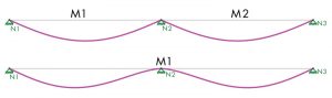
Early in the author’s career, he became a self-professed guru of RISA-3D (a structural engineering analysis and design software). An expertise in the software offered the ability to model complex structural networks, frames, etc. – a valuable bag of tricks for a young, aspiring engineer. Many colleagues at the firm had a hard time properly setting the boundary conditions with what was, at the time, fairly new software. The author’s experience taught him that when a model failed to work, the culprit was usually in the area of boundary conditions. Similarly, the culprit with a part of the structure being under-designed was also often due to improper boundary conditions and member-to-member fixities. The secret to success: the animated deflected shape. Deflected shapes tell a story, and animated shapes write a novel! Is the end of that cantilever deflecting as it should? Do you have a point on the structure flying off the screen? Does the continuous beam look like a sharp inverted “V” (mistake) or a swooping inverted “U” (correct) at the interior support? (see Figure) Make sure to view it from different planes, with isometric often being the most useful. Read the story that the deflected shape tells.
Deflection
We understand it well, but the general public and even many architects do not know that a beam must deflect in order to support a load. But one more thing is for sure: if your beam deflects enough such that it can be seen by the naked eye, you will be left trying to teach a course in structural design of beams to an uneducated audience who does not care about engineering principle. They just want the beam to be straight. To error check for this, look for long-span beams that are lightly loaded – beams where the self-weight is significant. This is especially true for beams that can be seen, like those being used as a decorative eyebrow or a storefront element. Check the total deflection. You will be surprised to see how often you will want to stiffen it, even if it does meet a reasonable deflection ratio, i.e., an “L-over.” Do any of the beams support masonry? Is the ceiling a flexible T-bar, or did the architect slip a rigid hard lid ceiling in there? Make sure the appropriate L-over has been used. Now, do you want to thicken the plot? Consider that which many an engineer often ignores – cumulative deflections. Here is an area where modeling a beam network in a program shines and hand calculations lag behind.
There you have it, Part 1 of three of Error Checking and the Black Box. Part 2 will discuss load paths, connections, torsion, temperature and shrinkage, and dissimilar materials.■