Geometric Characteristics of Spur Dike Scour under Clear-Water Scour Conditions
by
Li Zhang
1,2,*, 
Pengtao Wang
1,2,
Wenhai Yang
1,2,
Weiguang Zuo
2,
Xinhong Gu
2 and
Xiaoxiao Yang
2 1
Water Conservancy and Hydropower Engineering, Hohai University, Nanjing 210098, China
2
Water Institute of Civil Engineers, North China University of Water Resources and Electric Power, Zhengzhou 450046, China
*
Author to whom correspondence should be addressed.
Water 2018, 10(6), 680; https://doi.org/10.3390/w10060680
Submission received: 19 April 2018
/
Revised: 7 May 2018
/
Accepted: 15 May 2018
/
Published: 24 May 2018
(This article belongs to the Special Issue Water-Worked Bedload: Hydrodynamic and Mass Transport)
Abstract
:Factors such as flow and sediment characteristics affecting the spur dike’s local depth of erosion have yielded considerable research results, but there is little discussion of the geometry of the spur dike’s local scour holes. This study focuses on the spatial characteristics of the geometry of local scour holes in straight-wall spur dikes. The discussion shows that the spur dike arrangement clearly changes the plane geometry of the scour hole. The maximum scour depth has a power function relationship with the area of the scour hole and the scour hole-volume. Moreover, the ratio of the product of the maximum scour depth and the plane area of the scour hole to the scour hole-volume is a fixed constant. The average slope of upstream of the scour hole and along the axis direction of the spur dike is slightly larger than the angle of repose of the sediment, the slope distribution of the scour holes profiles presents an inverted “U” type, and its profile morphology and slope distribution have geometric similarity. This distribution also reflected that, the interaction between the downward flow and the horseshoe vortex inside the scour hole leads to the formation of a cusp.
1. Introduction
Spur dikes are a typical hydraulic structure building, which have the function of protecting river banks from flow scouring and improving the habitat area of aquatic organisms, and therefore, are widely used in river regulation and water ecological restoration projects, and so on. After the spur dike was arranged in the river, the original flow characteristics and sediment movement of the river section were changed, resulting in scouring of the riverbed around the spur dike. Discussion on the problem of scouring, on the one hand, it is conducive to predicting the geometric characteristics of scour hole, including the degree of vertical dimension and longitudinal dimension erosion, for the optimization of spur dike engineering parameters and design, etc. On the other hand, the physical environmental indicators near spur dikes, such as the deep pool/shoal, and the flow structure, are also the technical bases for improving the assessment of habitat area of aquatic organisms. In recent years, scholars pay more attention to the vertical dimension erosion degree of scour hole in spur dikes, that is, each physical factor affects the scour depth adjustment characteristic, but there is little discussion of the results of the morphology spatial dimension characteristic of scour holes; it is urgent to discuss this problem. The related research results undoubtedly provide technical support for the river regulation and ecological restoration of spur dikes.
Maximum scour depth is one of the important parameters of engineering design. There is a consensus that the characteristics of flow and sediment, the size and type of buildings, etc., affect the law of maximum scour depth [1,2,3]. In addition to the parameters of the maximum scour depth, the geometric parameters of scour holes in spur dikes also include the plane area of scour hole, scour hole-volume, and plane geometry dimension, etc. Kuhnle et al. [4] pointed out that the ratio of scour hole-volume and the maximum scour depth of a spur dike is approximately constant, due to the impact of flow shallowness and the alignment angle. However, Fael et al. [5] pointed out that the ratio of scour hole-volume and the maximum scour depth increases with the increase of flow shallowness, and further raise an empirical formula for predicting the plane area and volume of scour hole by maximum scour depth. Haltigin et al. [6] predicted the geometric characteristics of scour hole according to the geometry characteristic dimension of scour holes. Williams et al. [7] pointed out the flow shallowness and relative coarseness did not affect the geometric characteristics of the scour hole, and the water resistance rate of the spur dike had an impact on it, however, the geometric characteristics of the scour hole affected by the water resistance rate were not discussed.
The angle of repose of sediment not only reflects the morphology of the scour hole, but also involves the prediction of it and the discussion of the local vortex characteristics [8,9]. One aspect is the discussion of the relationship between the angle of repose of sediment and the slope of the scour hole. For example, Kothyari [10] proposed that the profile slope of a scour hole is equal to the angle of repose of sediment. Zhang [11] pointed out that when the scour reached the equilibrium state, the slope upstream and downstream of a spur dike remains relatively stable, and the slope is approximately the angle of repose of sediment. Karami [12] considered that not only the average slope upstream of the scour hole was equal to the angle of repose of sediment, but also the upstream slope of the scour hole was steeper than the downstream. Some scholars use numerical simulation techniques to predict the depth and shape of local scour holes, based on the feature that the angle of repose of sediment is equal to the slope of the scour hole [8]. However, Zhang [13] pointed out that the angle of repose of sediment is slightly greater than the slope of scour hole. The second is the discussion of the morphological characteristics of the scour holes. Such as Muzzammil [9], who pointed out the existence of a cusp and two distinct slopes in the scour hole. Diab et al. [14] paid attention to the morphological characteristics of each azimuthal of the local scour hole of the bridge pier, and pointed out that the profile of the various scour holes in the pier had similar characteristics. Williams et al. [7] pointed out that the whole process of scour evolution remained similar. Bouratsis et al. [15] discussed, in detail, the average slope of each azimuthal of the bridge pier scour hole, and considered that the average slope distribution characteristics of all azimuths present approximately a sine function. Although there are many discussions, they are discussed in terms of the average slope of the scour hole profile, and the relationship between the slope of scour hole profile and the angle of repose of sediment is still debated, and the profile slope distribution feature is also indistinct.
To sum up, the morphological characteristics of the scour hole are a specific problem in the study of scour mechanisms, which involve different physical factors affecting the erosion characteristics of two dimensional directions of the scour holes, and are still indistinct. In this paper, we choose spur dike as the research object, and discuss this specific problem by carrying out flume experiments and improving the observation method.
2. Experimental Setup and Procedures
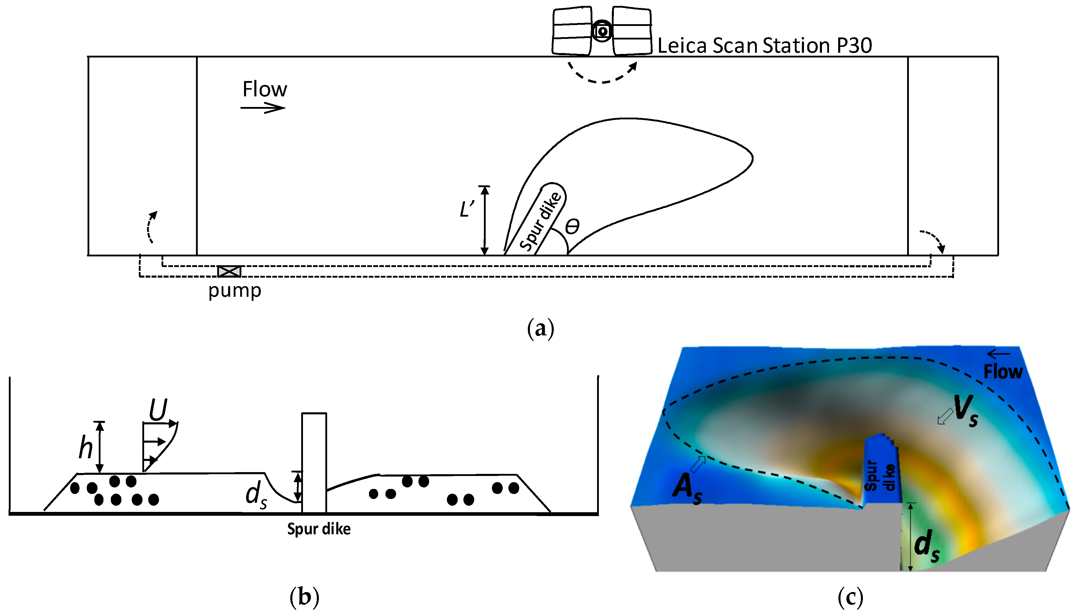
The experiment was carried out in a circular flume, whereby the flume is 50 m long and 0.8 m wide. The experimental observation area was located in the middle of the flume, and was 30 m long. The sand adopted uniform sand, and the median particle size d50 is 0.2 mm, 0.7 mm, and 1.0 mm respectively; the non-uniform coefficient = 1.14~1.3. The schematic diagram of experimental plane and profile are shown in Figure 1.
In the practical engineering application, three typical alignment forms are used in the spur dike: θ = 90°, θ < 90°, and θ > 90°; the θ > 90° alignment, is often applied to submerged spur dikes, while the other two types of alignment are applied to non-submerged spur dikes, such as the Yellow River and the Yangtze River, the spur dikes in θ = 90° and θ < 90°, as the main alignment. To make the discussion more fitting to the actual engineering application, this study focuses on the non-submerged types, so the design of spur dike angles of alignment were θ = 90°, θ = 60°, and θ = 30°. The length of the spur dikes, L, are respectively 0.12 m and 0.2 m. The structure of spur dikes adopted a vertical wall spur dike with semi-circular type.
Flow depth of spur dike upstream h = 0.08~0.3 m, with clear-water scouring conditions, and a designed flow intensity U/Uc = 0.85, the upstream flow velocity U was measured by an acoustic Doppler velocimeter (ADV); Uc is the incipient velocity of sediment, calculated using the Shamov formula [16]. The design of flow, sediment characteristics, and working conditions are shown in Table 1.
where is the density of sediment; is the density of water; g is the acceleration of gravity; d50 is the median diameter of sediment; h is the depth of water.
Before the experiment, the bed of the experimental area is kept flat, and the water was slowly stored in the flume to the design depth, adjusting the speed of the axial flow pump, reaching the design flow strength, and carrying out the scour experiment. The local scour of each working condition was 49 h. After the experiment, the water in the sink was slowly vented. After the river bed was dried, the experimental terrain of the local scour hole was collected.
Observation of the area and volume of scour holes in hydraulic structures is more dependent on the improvement of measuring methods; In recent years, measurement techniques, such as LDS (laser distance sensor) [14,17] and high-resolution 3-D monitoring system [18], have been gradually applied to the observation of scour hole morphology. In order to improve the morphology of scour hole of spur dike, a high-speed laser scanner (Leica Scan Station P30) was used to collect the experimental profiles, and its scanning noise accuracy was 0.5 mm @ 50 m; The maximum ranging error within 1 km does not exceed 1.2 mm. Based on the experimental profiles point cloud data, the morphology of the scour holes of spur dikes were refined, as shown in Figure 1c, using Cyclone, Surfer, and other related computation programs to extract the geometric characteristics parameters of scour holes.
The scour depth, the plane area, and scour hole-volume were all calculated using the base surface of the spur dike without the occurrence of the bed surface. The sand waves and the smaller scouring holes downstream were neglected.
3. Results and Discussion
3.1. Scour Depth
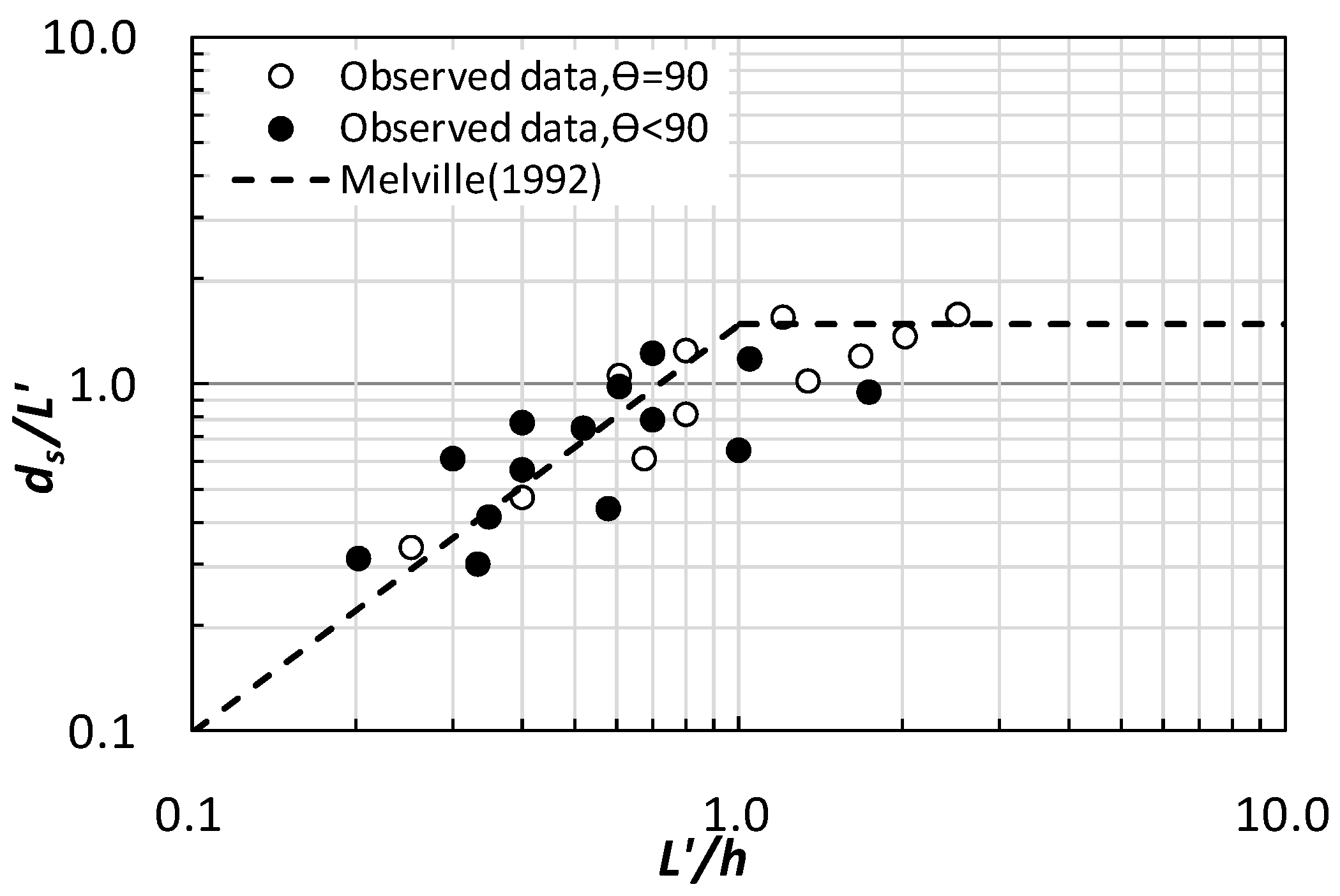
The adjustment characteristics of scour depth of spur dike have already got a consensus [1,2,13,19]. Melville [1] thought that for short spur dikes, ds/L = 2Ks; for intermediate spur dikes, ds/(Lh)0.5 = 2KsKϴ. Ks is the structural shape coefficient, and Kϴ is the alignment angle coefficient. However, when θ = 90°, L = L’; when θ ≠ 90°, L’ = L × sin θ. The L’ is the length of the spur dike projection. In view of this, for the local scour depth of the short spur dikes, the alignment angle coefficient also needs to be considered. According to the results of experimental observations of various working conditions, the adjustment laws of local depth of erosion are shown in Figure 2.
For short spur dikes, ds/L’ increases as L’/h increases gradually. Regression analysis shows that the slope of the linear relationship is 1.5, close to 2Ks, and for the straight-wall spur dikes, Ks = 0.75. Since the short spur dike only considers the structural shape coefficient, and does not consider the alignment angle coefficient, and when θ = 90°, Kθ = 1.0; θ = 60°, Kθ = 0.96; θ = 30°, Kθ = 0.92. After calculation and correction, it can be seen that the adjustment law is similar to the θ = 90° arrangement. For the intermediate spur dikes, the upper limit is close to 2KsKϴ as the L’/h is gradually increased, and is still 1.5.
Based on the above, it is considered that the experimental observations are consistent with the existing research results; in addition, for the short spur dike, the prediction of the local maximum depth of scour and the influence of the alignment angle must also be considered.
3.2. Prediction of Plane Area and Volume of Scour Hole
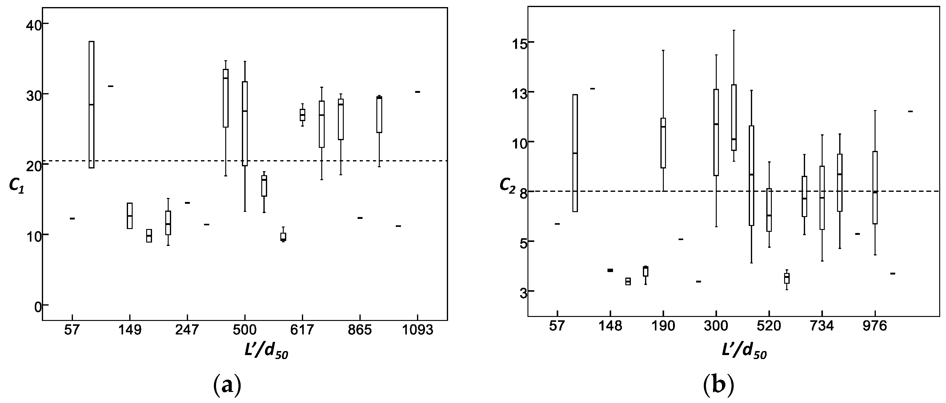
Based on the principle of dimensionality harmony, the form of As ~ ds2 and Vs ~ ds3 are usually used to discuss or predict the plane area and scour hole-volume by the maximum scour depth [5,20,21,22]. In order to facilitate the discussion of this problem, here are the formulas of As ~ ds2; Vs ~ ds3 is written as the power function relation, that is, As = C1 ds2; Vs = C2 ds3, where C1, C2 is the undetermined coefficient, respectively, and its value is related to the influencing factors. For any form of alignment, taking into account the experimental observation results and the existing research results (Table 1 and Table 2), C1, C2 values and relative coarseness adjustment characteristics can be obtained, as shown in Figure 3.
From the statistical data in Table 1 and Table 2, seeing that L’/d50 = 57 ~ 1094; h/L’ = 0.2~21.5. Affected by this, C1 and C2 have a slightly larger range of fluctuations, the averages are 20.5 and 8.0 respectively, as shown in Figure 3. With regard to the classification of spur dike type [1], it is considered that this result is also applicable to short and intermediate spur dikes.
Regarding scour hole plane area and volume prediction, due to the different impact factors, the research results on the value of the coefficient are not uniform. For example, Kuhnle [23] considered C2 = 12.11; Rodrigue [22] considered C2 = 3.87, and the difference is slightly larger. According to the C1 and C2 adjustment characteristics, C1 = 20.5 and C2 = 8.0 are selected, and the plane area and volume of the scour holes are predicted according to the maximum scour depth.
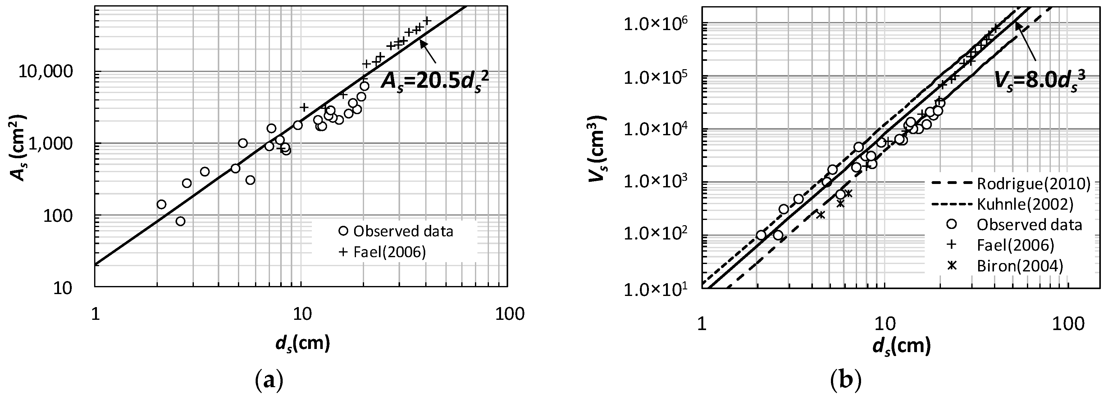
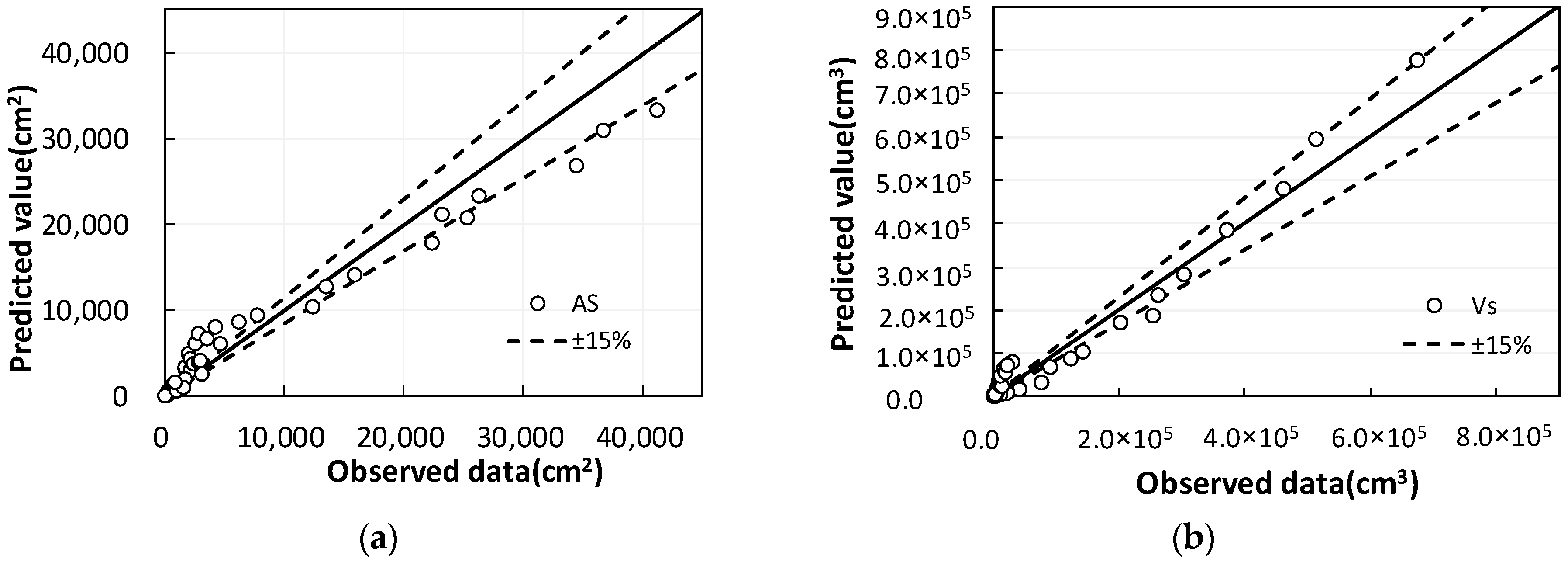
As can be seen from Figure 4, As = 20.5 ds2 and Vs = 8.0 ds3 can be used to predict the plane area and volume of scour holes by the maximum scour depth.
The error in predicting the plane area of the scour hole by using the maximum scour depth is slightly larger in contrast; this is because smaller scour holes occur downstream of scour holes when sediment particles are thinner (e.g., d50 = 0.2 mm). Where, ignored the impact of these small scour holes, which are basically within the range of ±15%, which is considered reasonable; see Figure 5.
3.3. The Morphology of Scour Holes
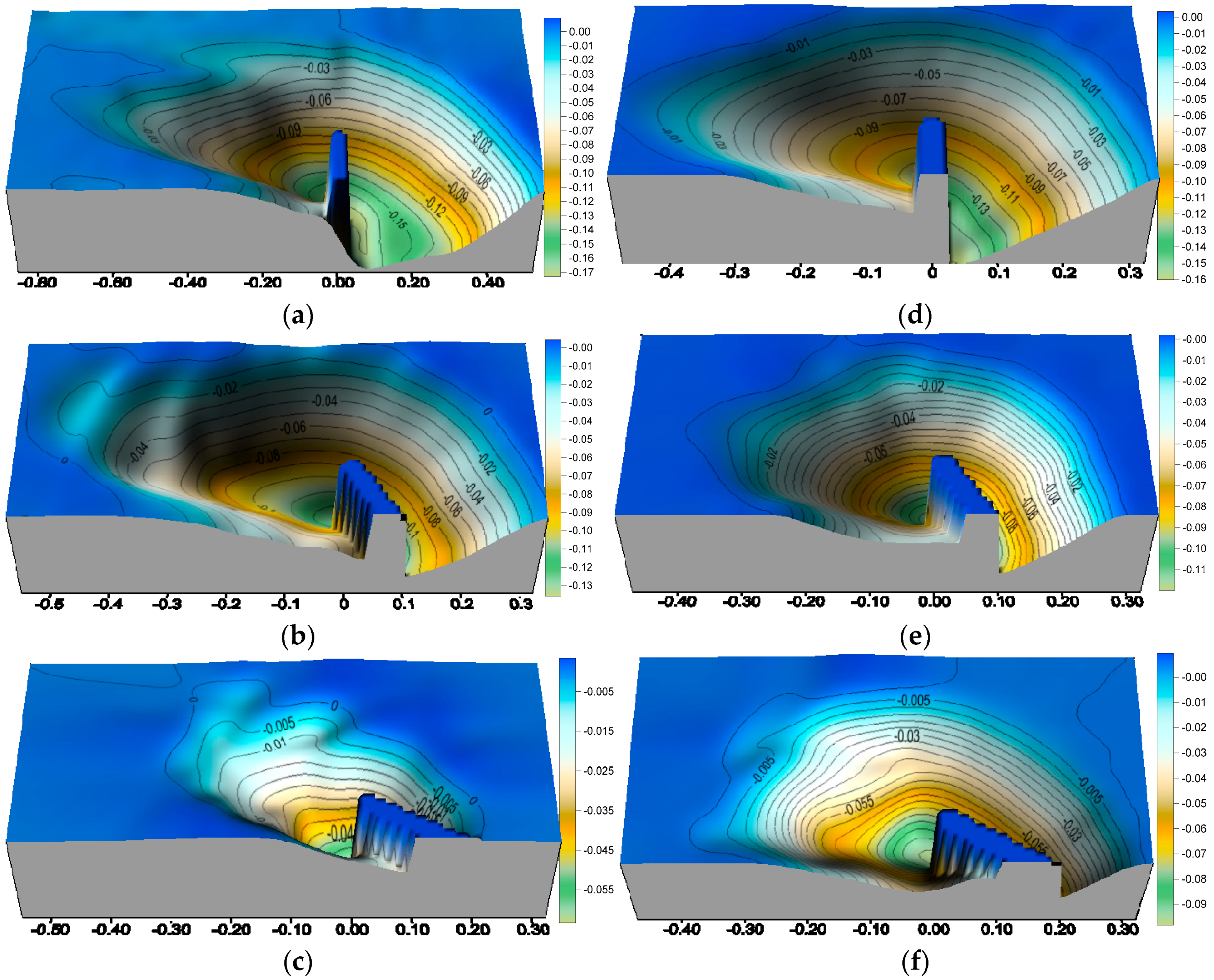
Due to the fact that the alignment of the spur dike changes the erosion of longitudinal dimension scour holes, it is therefore bound to cause changes in the morphology of scour hole. In order to better understand the scour morphology of spur dike, the three-dimensional morphology of the scour hole was reconstructed and visualized according to the experimental point cloud data of each condition. Shown in Figure 6 are selected typical conditions to display.
For the non-cohesive sand, the morphology of the scour hole in the spur dike is regular and smooth [24]. This phenomenon can also be observed for the scour hole downstream of a rigid bed for non-cohesive sand, while for cohesive materials, the scoured bed forms a non-regular pattern [25]. With the decrease of alignment angle, the position of maximum scour depth obviously changed, and its plane shape gradually changed from oval to triangle. The presence of sand waves downstream from the scour hole was also observed. However, because the bed surface that has not been flushed is used as the reference plane, the sand waves above the reference plane are ignored during the calculation of the volume and other parameters, and the visualization of the local scour hole geometry.
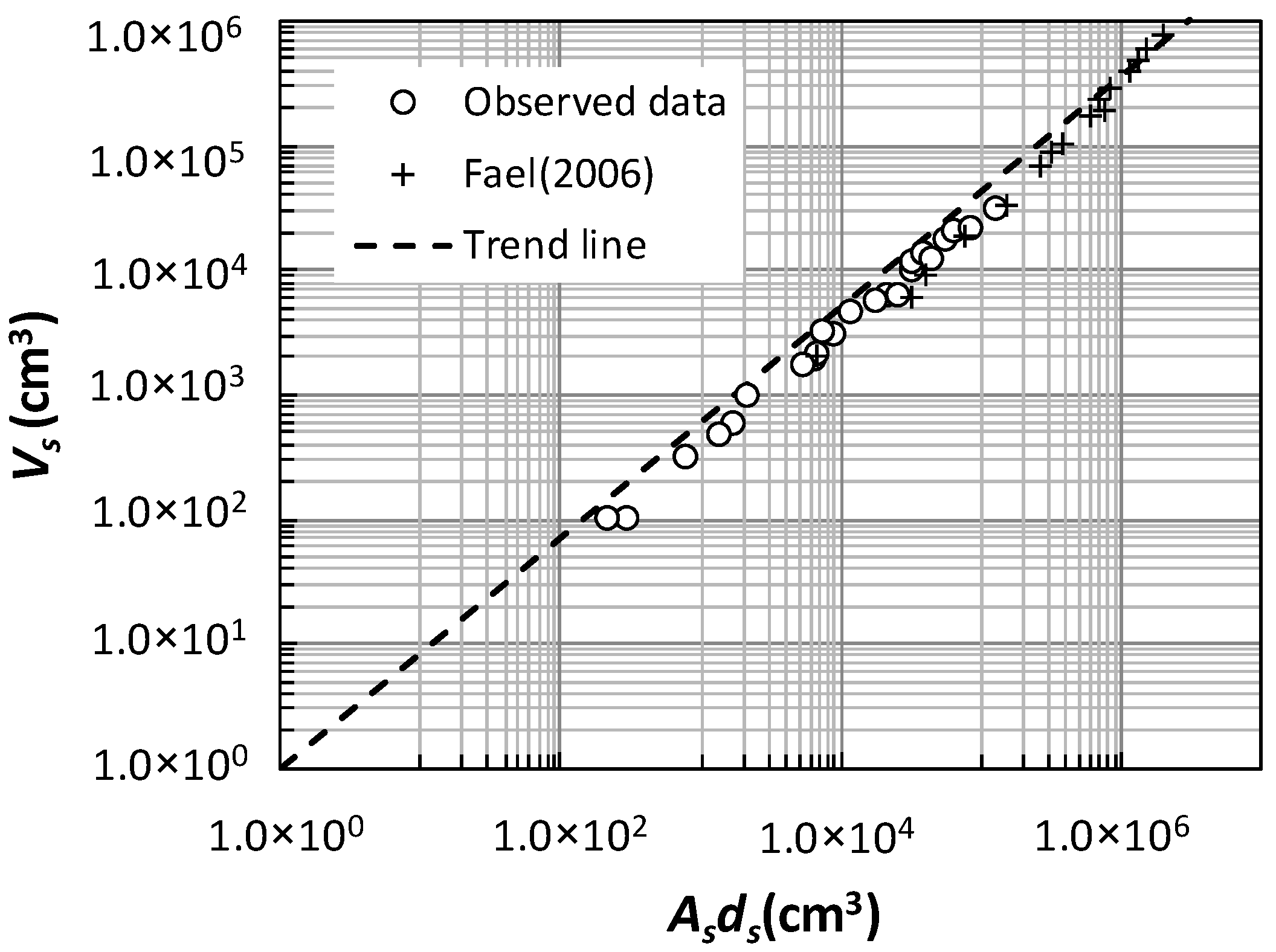
In three-dimensional geometry space, the scour hole-volume is equal to the product of the plane area of the scour hole and the maximum scour depth, that is, Vs ~ Asds, but the morphology of the scour hole is not regular in geometry. The ratio between Vs and Asds is still indistinct. Based on the results of experimental observation and previous research, the regulation laws of Vs and Asds, under the influence of various factors, are discussed and defined. See Table 1 and Figure 7.
The scour is in equilibrium state, and there is a linear relationship between Vs and Asds. Under the influence of those factors, the slope of the linear relationship is the constant of Vs/Asds, and regression analysis showed that its value was 0.32; in addition, we easily found that C1 and C2 mean ratio is also closer to this constant. Therefore, it can be concluded that the scour hole-volume has a proportional constant with the product of the plane area and the maximum scour depth, and this characteristic also reflects the geometric similarity of the scour hole morphology, which can also be seen from Figure 6.
3.4. The Profile Morphology of the Scour Holes
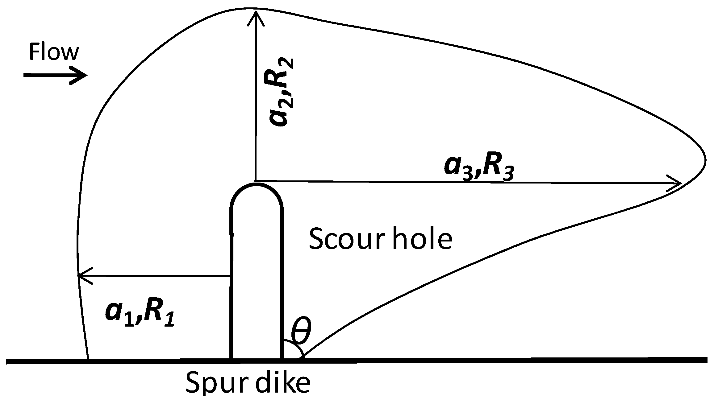
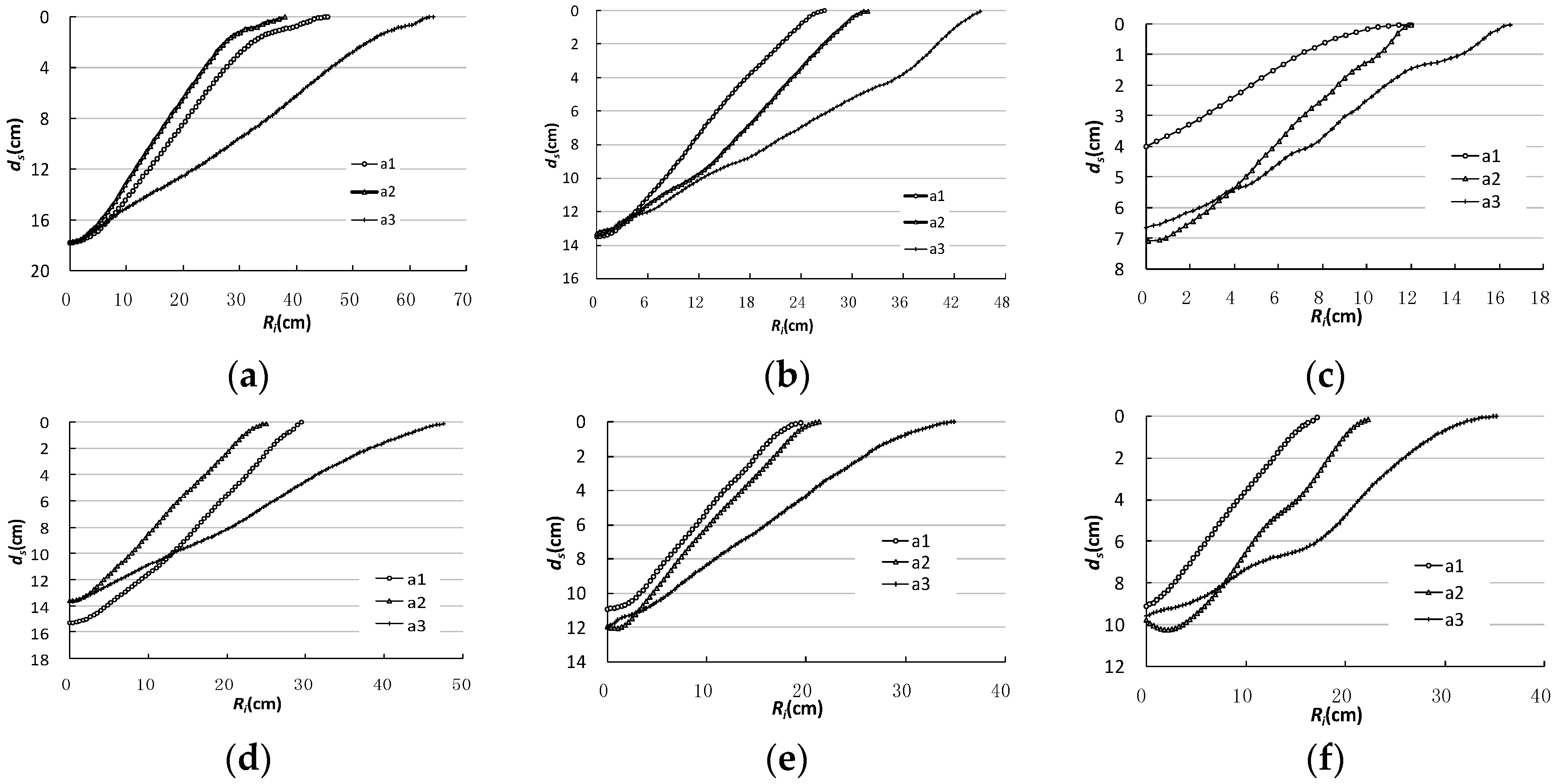
According to the experimental profile of each case, the scour hole profiles of each azimuthal were extracted. The azimuthal alignment is shown in Figure 8, where, αI is the azimuth, i = 1, 2, 3; α1 is defined as scour hole upstream; α2 is defined as along the spur dike axis direction; and α3 is defined as the downstream of the scour hole. Ri is the radius of the scour hole corresponding to each azimuthal angle, that is, the width of the scour hole plane.
Notice, according to Section 3.1 relative coarseness and scouring depth adjustment law, the two types of alignment θ = 90° and θ < 90° were chosen, respectively, and the morphology of the profiles of the scour holes are shown in different directions, as shown in Figure 9.
As can be seen from Figure 9a–f, compared with a1, a2, and a3 three-dimensional profile shape of the scour hole, it can be found that upstream of the scour hole and along the axis direction of the spur dike, the scour hole radius and the profiles are relatively close; downstream of scour hole, the radius is relatively increased, and the slope was significantly slower. Comparing the influence on relative coarseness and the alignment angle of spur dikes, although scour depth and the azimuth of the scour holes radiuses have obvious differences, upstream of scour hole and along the axis direction of spur dike, the profile morphology is similar; the downstream profile of scour holes are also similar. Comparing the scour depth of each azimuth, we see that with the decrease of alignment angle, the position of maximum scour depth gradually transits from the upstream of the spur dike to the head of it.
Diab [14] discussed the different azimuthal profile morphologies of bridge pier scour holes, and pointed out that their profile morphology was geometrically similar. Williams [7] pointed out that the relative coarseness did not affect the geometric similarity of pier scour holes profile morphology.
Results of Tafarojnoruz [26] also show that some kinds of pier scour countermeasures, e.g., pier slot, may not significantly change the similarity of the scour shape.
Comparing the scour hole profile morphology characteristics of the spur dikes, all of them have geometric similarity, which shows that the relative coarseness and spur dike alignment do not affect the profile morphology characteristics of the hole, and they have geometric similarity.
3.5. The Profiles Slope of the Scour Holes
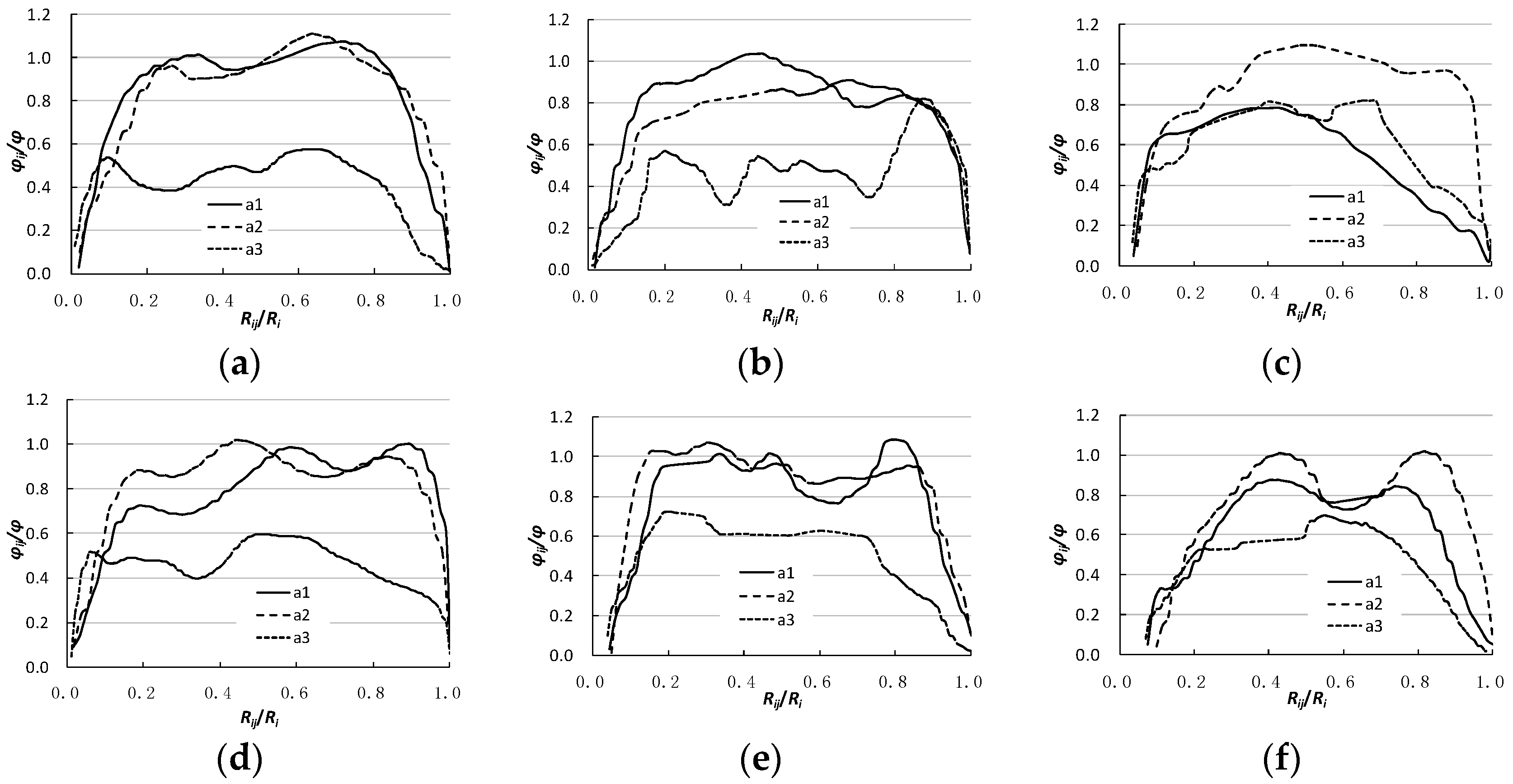
According to the profile morphology characteristics of each azimuthal scour hole, in accordance with the trigonometric relationship, the slope (in terms of angle, the same as below) of any point of the scour hole profiles is calculated piece by piece, according to the trigonometric function, that is, φij = arctan (Δds/ΔRij), where, Δds is the vertical height difference between adjacent points of scour hole profiles; ΔRij is the horizontal distance between two adjacent points; φij is the slope value of any point on the slope of the scour holes, i = 1, 2, 3, respectively, corresponding to α1, α2, α3; and j is the number of calculation, j = 1, 2, 3, …, n.
The sediment median particle size is unchanged, and the angle of repose is constant. The sediment angle of repose, which references [13], where d50 = 0.2 mm, φ = 33.1°; d50 = 0.7 mm, φ = 34.8°; d50 = 1.1 mm, φ = 35.4°; and where φ is the sediment angle of repose.
The dimensionless parameter φij/φ undoubtedly reflects the difference between the profile slopes and the angle of repose of sediment; the dimensionless parameter Rij/Ri is normalized to the radius of each scour hole. Therefore, the dimensionless parameter Rij/Ri and φij/φ relationship pare reflect the azimuth of the profile slopes distribution characteristics. The profile slope distribution of each azimuth is shown in Figure 10.
Comparing the profile slopes at each azimuthal scour hole, it is easily found that regarding the scour hole upstream and along the axis direction of spur dike, the scour hole profile steepness is closer; in the scour hole downstream, profile slope morphology is similar, but the slope has obviously slowed down. Comparing the impact of relative coarseness and the alignment angle, the relationship between Rij/Ri and φij/φ shows that although the slope distribution is slightly different, but presents from small to large, and then the trend is reduced, showing an inverted “U” distribution. This shows that profile slopes distribution of scour hole also has geometric similarity.
Both for the bridge piers and the spur dikes, the existing research results indicated that the average slope upstream of the scour hole is approximately equal to the sediment repose angle, and the profile slopes upstream are greater than those downstream [12,27]. The φij/φ ratio indicates that the slope of a certain distance in the scour hole is approximately equal to the sediment repose angle, and the average value is smaller than the sediment repose angle. Zhang [13] pointed out that the slope ratio of upstream and downstream angles of the scour hole is constant, about 0.5. The experimental results further indicate that the ratio of the average slope upstream and along the axis direction of spur dike, and the average slope downstream of the scour hole, with a mean of 0.6, and the discussion results, are relatively close.
Unger and Hager [28] pointed that the interaction between the downward flow and the horseshoe vortex inside the scour hole leads to the formation of a cusp, separating the region in the scour hole mainly shaped by the downward-flow and the region shaped by the horseshoe vortex and the separation vortexes. Indeed, there is a cusp in the slope of the scour hole, which leads to a sudden change in the slope of the scour hole. The overall shape is an inverted “U” pattern. The scour mechanism depends fundamentally on the downward flow, and not on the intensity of the horseshoe vortex, as argued by Shen et al. [29]. However, considering the slope distribution characteristics of the scour hole, it is closely related to the distribution pattern of the horseshoe vortex system, and the eddy current size and intensity.
4. Conclusions
Based on the flume experiment, the effect of relative coarseness and the alignment of spur dikes on the morphological characteristics of scour hole are discussed. The results show the following:
Under clear-water scour conditions, for the vertical wall spur dike with semi-circular type. Using C1 = 20.5 and C2 = 8.0, it is reasonable to predict the plane area and volume of the scour hole by maximum scour depth. There is a fixed proportional relationship between the product of the plane area, and the maximum scour depth and the scour hole-volume, and the constant is 0.32, which has geometric similarity. With the decrease of alignment angle, the position of maximum scour depth gradually approached the head of spur dike. The arrangement of the spur dike significantly changed the position of the local maximum scour depth and the plane shape of the scour hole. With the decrease of alignment angle, there is a gradual transition from an approximate ellipse to an approximately triangular shape. The position of maximum scour depth gradually approached the head of spur dikes.
Affected by the relative coarseness and the alignment of the spur dikes, the average slope upstream of the scour hole and along the axis direction of the spur dike is slightly larger than the angle of repose of the sediment, and both are steeper than the downstream angle of the scour hole; the ratio of the average slope of the upstream and along the axis direction of spur dike, and the average slope downstream of the scour hole, ranged from 0.5 to 0.86. The slope distribution of the scour hole profiles present an inverted “U” type distribution, and the profile morphology and slope distribution have geometric similarity.
Author Contributions
Li Zhang, Pengtao Wang conceived the experiments; Pengtao Wang and Wenhai Yang designed and performed the experiments; XinhongGu and XiaoxiaoYang recorded experimental data; Weiguang Zuo analyzed the data and drew pictures; Li Zhang analysis and the interpretation of the results, wrote the paper.
Acknowledgments
This work was funded by the National Natural Science Foundation of China (51579103); Funding for the open project fund of Key Laboratory of the Yellow River sediment of the Ministry of Water Resources (201805).
Conflicts of Interest
The authors declare no conflicts of interest.
References
- Melville, B.W. Local scour at bridge abutments. J. Hydraul. Eng. 1992, 118, 615–631. [Google Scholar] [CrossRef]
- Melville, B.W. Bridge abutment scour in compound channels. J. Hydraul. Eng. 1995, 121, 863–868. [Google Scholar] [CrossRef]
- Lee, S.O.; Sturm, T.W. Effect of sediment size on physical modeling of bridge pier scour. J. Hydraul. Eng. 2009, 135, 793–802. [Google Scholar] [CrossRef]
- Kuhnle, R.A.; Alonso, C.V.; Shields, F.D., Jr. Local scour associated with angled spur dikes. J. Hydraul. Eng. 2002, 128, 1087–1093. [Google Scholar] [CrossRef]
- Fael, C.M.S.; Simarro-Grande, G.; Martín-Vide, J.P.; Cardoso, A.H. Local scour at vertical-wall abutments under clear-water flow conditions. Water Resour. Res. 2006, 42. [Google Scholar] [CrossRef]
- Haltigin, T.W.; Biron, P.M.; Lapointe, M.F. Predicting equilibrium scour-hole geometry near angled stream deflectors using a three-dimensional numerical flow model. J. Hydraul. Eng. 2007, 133, 983–988. [Google Scholar] [CrossRef]
- Williams, P.D. Scale Effects on Design Estimation of Scour Depths at Piers. Ph.D. Thesis, The University of Windsor, Windsor, ON, Canada, 2014. [Google Scholar]
- Bihs, H.; Olsen, N.R.B. Numerical modeling of abutment scour with the focus on the incipient motion on sloping beds. J. Hydraul. Eng. 2011, 137, 1287–1292. [Google Scholar] [CrossRef]
- Muzzammil, M.; Gangadhariah, T. The mean characteristics of horseshoe vortex at a cylindrical pier. J. Hydraul. Res. 2003, 41, 285–297. [Google Scholar] [CrossRef]
- Kothyari, U.; Garde, R.; Ranga Raju, K. Temporal variation of scour around circular bridge piers. J. Hydraul. Eng. 1992, 118, 1091–1106. [Google Scholar] [CrossRef]
- Zhang, H.; Nakagawa, H.; Kawaike, K.; Baba, Y. Experiment and simulation of turbulent flow in local scour around a spur dyke. Int. J. Sediment Res. 2009, 24, 33–45. [Google Scholar] [CrossRef]
- Karami, H.; Ardeshir, A.; Saneie, M.; Salamatian, S.A. Prediction of time variation of scour depth around spur dikes using neural networks. J. Hydroinform. 2012, 14, 180–191. [Google Scholar] [CrossRef]
- Zhang, L.; Sun, K.Z.; Xu, D.P. Morphological evolution of spur dike local scour hole and the scour balance critical condition. J. Hydraul. Eng. 2017, 48, 545–550. [Google Scholar]
- Diab, R.M.A.E.A. Experimental Investigation on Scouring around Piers of Different Shape and Alignment in Gravel; TU Darmstadt: Darmstadt, Germany, 2011. [Google Scholar]
- Bouratsis, P.; Diplas, P.; Dancey, C.L.; Apsilidis, N. Quantitative Spatio-Temporal Characterization of Scour at the Base of a Cylinder. Water 2017, 9, 227. [Google Scholar] [CrossRef]
- Wang, H.; Tang, H.W.; Xiao, J.F.; Wang, Y.; Jiang, S. Clear-water local scouring around three piers in a tandem arrangement. Sci. China Technol. Sci. 2016, 59, 888–896. [Google Scholar] [CrossRef]
- Oscar, L.P.; fleger, F.; Zanke, U. Characteristics of developing scour-holes at a sand-embedded cylinder. Int. J. Sediment Res. 2008, 23, 258–266. [Google Scholar]
- Bouratsis, P.P.; Diplas, P.; Dancey, C.L.; Apsilidis, N. High-resolution 3-D monitoring of evolving sediment beds. Water Resour. Res. 2013, 49, 977–992. [Google Scholar] [CrossRef]
- Coleman, S.E.; Lauchlan, C.S.; Melville, B.W. Clear-water scour development at bridge abutments. J. Hydraul. Res. 2003, 41, 521–531. [Google Scholar] [CrossRef]
- Cheng, N.S.; Chiew, Y.M.; Chen, X. Scaling an alysis of Pier-Scouring Processes. J. Eng. Mech. 2016. [Google Scholar] [CrossRef]
- Biron, P.M.; Robson, C.; Lapointe, M.F.; Gaskin, S.J. Deflector designs for fish habitat restoration. Environ. Manag. 2004, 33, 25–35. [Google Scholar] [CrossRef] [PubMed]
- Rodrigue-Gervais, K.; Biron, P.M.; Lapointe, M.F. Temporal development of scour holes around submerged stream deflectors. J. Hydraul. Eng. 2010, 137, 781–785. [Google Scholar] [CrossRef]
- Kuhnle, R.A.; Alonso, C.V.; Shields, F.D. Geometry of scour holes associated with 90 spur dikes. J. Hydraul. Eng. 1999, 125, 972–978. [Google Scholar] [CrossRef]
- Debnath, K.; Chaudhuri, S. Effect of suspended sediment concentration on local scour around cylinder for clay-sand mixed sediment beds. Eng. Geol. 2011, 117, 236–245. [Google Scholar] [CrossRef]
- Dodaro, G.; Tafarojnoruz, A.; Sciortino, G.; Adduce, C. Modified Einstein sediment transport method to simulate the local Scour evolution downstream of a rigid bed. J. Hydraul. Eng. 2016, 142, 04016041. [Google Scholar] [CrossRef]
- Tafarojnoruz, A.; Gaudio, R.; Calomino, F. Evaluation of flow-altering countermeasures against bridge pier scour. J. Hydraul. Eng. 2012, 138, 297–305. [Google Scholar] [CrossRef]
- Barbhuiya, A.K.; Dey, S. Local scour at abutments: A review. Sadhana 2004, 29, 449–476. [Google Scholar] [CrossRef]
- Unger, J.; Hager, W.H. Down-flow and horseshoe vortex characteristics of sediment embedded bridge piers. Exp. Fluids 2007, 42, 1–19. [Google Scholar] [CrossRef]
- Shen, H.W.; Schneider, V.R.; Karaki, S. Local scour around bridge piers. J. Hydraul. Div. Proc. Am. Soc. Civ. Eng. 1969, 95, 1919–1940. [Google Scholar]
Figure 1.
(a) Schematic diagram of flume alignment; (b) Schematic diagram of profiles alignment; (c) Geometric characteristics parameters.
Figure 1.
(a) Schematic diagram of flume alignment; (b) Schematic diagram of profiles alignment; (c) Geometric characteristics parameters.

Figure 2.
Local scour depth adjustment characteristics.

Figure 3.
(a) C1 adjustment characteristics; (b) C2 adjustment characteristics.

Figure 4.
(a) The relationship between maximum scour depth and plane area of scour hole; (b) The relationship between maximum scour depth and scour hole-volume.
Figure 4.
(a) The relationship between maximum scour depth and plane area of scour hole; (b) The relationship between maximum scour depth and scour hole-volume.

Figure 5.
(a) The error distribution of scour holes’ plane area; (b) The error distribution of scour hole-volume.
Figure 5.
(a) The error distribution of scour holes’ plane area; (b) The error distribution of scour hole-volume.

Figure 6.
Three-dimensional structure of scour holes in typical conditions (axis unit: m). (a) d50 = 1.1 mm; L’/d50 = 182; ϴ = 90°; (b) d50 = 0.2 mm; L’/d50 = 520; ϴ = 60°; (c) d50 = 0.2 mm; L’/d50 = 300; ϴ = 30°; (d) d50 = 0.7 mm; L’/d50 = 171; ϴ = 90°; (e) d50 = 0.7 mm; L’/d50 = 149; ϴ = 60°; (f) d50 = 0.7 mm; L’/d50 = 86; ϴ = 30°.

Figure 7.
The relationship between the maximum scour depth and the scour hole-volume.

Figure 8.
Schematic diagram of each azimuthal plane alignment of the scour holes.

Figure 9.
The profile morphological characteristics of each azimuthal of the scour holes. (a) d50 = 1.1 mm; L’/d50 = 182; θ = 90°; (b) d50 = 0.2 mm; L’/d50 = 520; θ = 60°; (c) d50 = 0.2 mm; L’/d50 = 300; θ = 30°; (d) d50 = 0.7 mm; L’/d50 = 171; θ = 90°; (e) d50 = 0.7 mm; L’/d50 = 149; θ = 60°; (f) d50 = 0.7 mm; L’/d50 = 86; θ = 30°.

Figure 10.
The profile slope distribution of each azimuth of the scour holes. (a) d50 = 1.1 mm; L’/d50 = 182; θ = 90°; (b) d50 = 0.2 mm; L’/d50 = 520; θ = 60°; (c) d50 = 0.2 mm; L’/d50 = 300; θ = 30°; (d) d50 = 0.7 mm; L’/d50 = 171; θ = 90°; (e) d50 = 0.7 mm; L’/d50 = 149; θ = 60°; (f) d50 = 0.7 mm; L’/d50 = 86; θ = 30°.


Table 1.
Flow conditions and geometric parameters.
| Case | Parameter | Non-Dimensional Parameter | |||||||||
|---|---|---|---|---|---|---|---|---|---|---|---|
| Length L (m) | Alignment Angle θ (°) | Sediment Size d50 (mm) | Flow Depth h (mm) | Scour Depth ds (cm) | Area of Plane AS (cm2) | Volume VS (cm3) | L’/d50 | L’/h | AS/ds2 | VS/ds3 | |
| A1 | 0.12 | 90 | 0.2 | 0.1 | 17.0 | 2589.85 | 12,608.42 | 600 | 1.2 | 8.961 | 2.566 |
| A2 | 60 | 13.5 | 2393.81 | 11,565.47 | 520 | 1.04 | 13.135 | 4.701 | |||
| A3 | 30 | 7.0 | 897.66 | 1963.36 | 300 | 0.6 | 18.320 | 5.724 | |||
| A4 | 90 | 0.15 | 8.5 | 798.87 | 2186.84 | 600 | 0.8 | 11.057 | 3.561 | ||
| A5 | 60 | 7.9 | 1108.11 | 3101.92 | 520 | 0.69 | 17.755 | 6.291 | |||
| A6 | 30 | 2.8 | 271.91 | 315.05 | 300 | 0.4 | 34.682 | 14.352 | |||
| A7 | 90 | 0.3 | 5.7 | 301.72 | 593.44 | 600 | 0.4 | 9.287 | 3.204 | ||
| A8 | 60 | 4.8 | 436.11 | 992.11 | 520 | 0.35 | 18.928 | 8.971 | |||
| A9 | 30 | 2.1 | 141.97 | 100.65 | 300 | 0.2 | 32.193 | 10.868 | |||
| A10 | 0.2 | 90 | 12.3 | 1692.79 | 6278.40 | 1000 | 0.67 | 11.189 | 3.374 | ||
| A11 | 60 | 8.4 | 870.28 | 3178.40 | 865 | 0.57 | 12.334 | 5.363 | |||
| A12 | 30 | 3.4 | 399.91 | 494.00 | 500 | 0.3 | 34.594 | 12.569 | |||
| B1 | 0.2 | 90 | 0.7 | 0.1 | 19.5 | 4337.44 | 22,029.48 | 286 | 2.0 | 11.407 | 2.971 |
| B2 | 60 | 13.9 | 2796.7 | 13,687.77 | 247 | 1.73 | 14.475 | 5.097 | |||
| B3 | 30 | 7.2 | 1610.18 | 4722.7 | 143 | 1.0 | 31.061 | 12.653 | |||
| B4 | 0.12 | 90 | 0.15 | 15.3 | 2085.74 | 10,079.63 | 171 | 0.8 | 8.910 | 2.814 | |
| B5 | 60 | 14.3 | 2216.03 | 10,156.05 | 149 | 0.69 | 10.837 | 3.473 | |||
| B6 | 30 | 5.2 | 1011.51 | 1736.57 | 86 | 0.4 | 37.408 | 12.350 | |||
| B7 | 0.12 | 90 | 0.2 | 12.6 | 1701.08 | 6287.63 | 171 | 0.6 | 137.408 | 3.143 | |
| B8 | 60 | 12.1 | 2112.84 | 6397.93 | 149 | 0.52 | 14.431 | 3.601 | |||
| B9 | 30 | 9.6 | 1793.41 | 5732.78 | 86 | 0.3 | 27.999 | 6.480 | |||
| B10 | 0.05 | 90 | 2.6 | 82.89 | 103.11 | 57 | 0.25 | 12.262 | 5.867 | ||
| S1 | 0.20 | 90 | 1.1 | 0.08 | 20.2 | 6169.60 | 30,927.71 | 182 | 2.50 | 15.120 | 3.752 |
| S2 | 0.20 | 90 | 0.12 | 18.6 | 2922.98 | 18,230.19 | 182 | 1.67 | 8.449 | 2.833 | |
| S3 | 0.20 | 90 | 0.15 | 17.8 | 3634.43 | 20,715.28 | 182 | 1.33 | 11.471 | 3.673 | |
Table 2.
Flow conditions and geometric parameters.
| Case | Parameter | Non-Dimensional Parameter | |||||||||
|---|---|---|---|---|---|---|---|---|---|---|---|
| Length L (m) | Alignment Angle ϴ (°) | Sediment Size d50 (mm) | Flow Depth h (mm) | Scour Depth ds (cm) | Area of Plane AS (cm2) | Volume VS (cm3) | L’/d50 | L’/h | AS/ds2 | VS/ds3 | |
| F1 | 140 | 90 | 1.28 | 6.5 | 40.7 | 50,100 | 776,000 | 1094 | 21.5 | 30.245 | 11.510 |
| F2 | 125 | 6.6 | 19.9 | 7770 | 34,000 | 977 | 18.9 | 19.621 | 4.314 | ||
| F3 | 125 | 6.9 | 29.4 | 25,370 | 189,000 | 977 | 18.1 | 29.351 | 7.437 | ||
| F4 | 125 | 6.6 | 37.2 | 41,160 | 595,000 | 977 | 18.9 | 29.743 | 11.558 | ||
| F5 | 109 | 7.0 | 16 | 4730 | 19,000 | 852 | 15.6 | 18.477 | 4.639 | ||
| F6 | 109 | 6.9 | 27.3 | 22,340 | 170,000 | 852 | 15.8 | 29.975 | 8.355 | ||
| F7 | 109 | 6.6 | 35.9 | 36,690 | 480,000 | 852 | 16.5 | 28.468 | 10.374 | ||
| F8 | 94 | 6.7 | 33.4 | 34,480 | 385,000 | 734 | 14.0 | 30.908 | 10.333 | ||
| F9 | 94 | 7.0 | 24.3 | 15,920 | 103,000 | 734 | 13.4 | 26.961 | 7.178 | ||
| F10 | 94 | 7.0 | 13.1 | 3050 | 9000 | 734 | 13.4 | 17.773 | 4.003 | ||
| F11 | 79 | 6.9 | 31.2 | 26,250 | 284,000 | 617 | 11.4 | 26.966 | 9.351 | ||
| F12 | 79 | 7.1 | 23.1 | 13,550 | 88,000 | 617 | 11.1 | 25.393 | 7.139 | ||
| F13 | 79 | 7.1 | 10.4 | 3090 | 6000 | 617 | 11.1 | 28.569 | 5.334 | ||
| F14 | 64 | 7.0 | 29.7 | 23,170 | 236,000 | 500 | 9.1 | 26.267 | 9.008 | ||
| F15 | 64 | 7.0 | 8 | 850 | 2000 | 500 | 9.1 | 13.281 | 3.906 | ||
| F16 | 64 | 7.2 | 20.8 | 12,450 | 69,000 | 500 | 8.9 | 28.777 | 7.668 | ||
| K1 | 30.5 | 45 | 0.8 | 30.2 | 18.99 | / | 106,700 | 381 | 1.39 | / | 15.581 |
| K2 | 30.5 | 45 | 18.6 | 22.41 | / | 113,800 | 381 | 0.86 | / | 10.112 | |
| K3 | 15.2 | 45 | 30.66 | 16.68 | / | 67,630 | 190 | 2.84 | / | 14.573 | |
| K4 | 15.2 | 45 | 30.7 | 26.69 | / | 185,280 | 190 | 2.84 | / | 9.745 | |
| K5 | 15.2 | 45 | 18.45 | 27.98 | / | 166,720 | 190 | 1.71 | / | 7.611 | |
| K6 | 15.2 | 45 | 18.49 | 17.16 | / | 55,690 | 190 | 1.71 | / | 11.021 | |
| K7 | 30.5 | 90 | 18.56 | 22.15 | / | 135,730 | 381 | 0.61 | / | 12.490 | |
| K8 | 30.5 | 90 | 30.0 | 25.68 | / | 197,600 | 381 | 0.98 | / | 11.668 | |
| K9 | 15.2 | 90 | 18.42 | 15.45 | / | 99,160 | 190 | 1.21 | / | 26.888 | |
| K10 | 15.2 | 90 | 18.63 | 9.29 | / | 26,500 | 190 | 1.23 | / | 33.052 | |
| K11 | 15.2 | 90 | 30.23 | 13.04 | / | 52,470 | 190 | 1.99 | / | 23.663 | |
| K12 | 15.2 | 90 | 30.72 | 16.2 | / | 109,130 | 190 | 2.02 | / | 25.668 | |
| K13 | 30.5 | 135 | 18.28 | 25.13 | / | 143,020 | 381 | 0.84 | / | 9.012 | |
| K14 | 15.2 | 135 | 18.38 | 30 | / | 202,510 | 190 | 1.70 | / | 7.500 | |
| K15 | 15.2 | 135 | 18.4 | 17 | / | 54,350 | 190 | 1.70 | / | 11.062 | |
| K16 | 15.2 | 135 | 30.43 | 20.9 | / | 95,530 | 190 | 2.82 | / | 10.464 | |
| K17 | 15.2 | 135 | 30.46 | 28.47 | / | 260,370 | 190 | 2.82 | / | 11.283 | |
© 2018 by the authors. Licensee MDPI, Basel, Switzerland. This article is an open access article distributed under the terms and conditions of the Creative Commons Attribution (CC BY) license (http://creativecommons.org/licenses/by/4.0/).
Share and Cite
MDPI and ACS Style
Zhang, L.; Wang, P.; Yang, W.; Zuo, W.; Gu, X.; Yang, X. Geometric Characteristics of Spur Dike Scour under Clear-Water Scour Conditions. Water 2018, 10, 680. https://doi.org/10.3390/w10060680
AMA Style
Zhang L, Wang P, Yang W, Zuo W, Gu X, Yang X. Geometric Characteristics of Spur Dike Scour under Clear-Water Scour Conditions. Water. 2018; 10(6):680. https://doi.org/10.3390/w10060680
Chicago/Turabian StyleZhang, Li, Pengtao Wang, Wenhai Yang, Weiguang Zuo, Xinhong Gu, and Xiaoxiao Yang. 2018. "Geometric Characteristics of Spur Dike Scour under Clear-Water Scour Conditions" Water 10, no. 6: 680. https://doi.org/10.3390/w10060680
Note that from the first issue of 2016, this journal uses article numbers instead of page numbers. See further details here.