Review

A Review of Fouling Mechanisms, Control Strategies and Real-Time Fouling Monitoring Techniques in Forward Osmosis

1
School of Civil and Environmental Engineering, University of Technology Sydney, 15 Broadway, Ultimo, NSW 2007, Australia
2
School of Chemical Engineering, Surrey University, Guildford GU2 7XH, Surrey, UK
3
Department of Civil and Architectural Engineering, Qatar University, P.O. Box 2713 Doha, Qatar
4
Department of Chemical Engineering Technology, College of Technological Studies, The Public Authority for Applied Education and Training (PAAET), P.O. Box 117, Sabah AlSalem 44010, Kuwait
*
Author to whom correspondence should be addressed.
Water 2019, 11(4), 695; https://doi.org/10.3390/w11040695
Submission received: 20 February 2019 / Revised: 31 March 2019 / Accepted: 2 April 2019 / Published: 4 April 2019
(This article belongs to the Special Issue Novel Forward Osmotic Process for Seawater and Wastewater Treatment)

Abstract

:
Forward osmosis has gained tremendous attention in the field of desalination and wastewater treatment. However, membrane fouling is an inevitable issue. Membrane fouling leads to flux decline, can cause operational problems and can result in negative consequences that can damage the membrane. Hereby, we attempt to review the different types of fouling in forward osmosis, cleaning and control strategies for fouling mitigation, and the impact of membrane hydrophilicity, charge and morphology on fouling. The fundamentals of biofouling, organic, colloidal and inorganic fouling are discussed with a focus on recent studies. We also review some of the in-situ real-time online fouling monitoring technologies for real-time fouling monitoring that can be applicable to future research on forward osmosis fouling studies. A brief discussion on critical flux and the coupled effects of fouling and concentration polarization is also provided.

Graphical Abstract

1. Introduction

One of the major issues affecting membrane performance in osmotically-driven membrane processes is fouling of the membrane. Membrane fouling occurs when particles or solutes accumulate on a membrane surface or inside the pores of the membranes [1]. These particles block pores, form a cake or gel-type layer on the membrane surface and reduce membrane permeability [2]. Fouling has several negative impacts on the membrane performance, such as inducing its own concentration polarization, weakening the membrane rejection properties and introducing additional hydraulic resistance [3]. Although membrane technologies have advantages over other mature technologies in water treatment, membrane fouling still is a major operational problem and needs further investigation [4].
Recently, forward osmosis (FO), has emerged as one of the promising membrane processes and alternatives to reverse osmosis (RO). FO uses an osmotic pressure gradient for permeation of water through a semi-permeable membrane. The major advantage of FO over other pressure driven membrane processes is that FO phenomena occurs spontaneously, without the need of any hydraulic pressure [5]. Pressure driven processes, such as reverse Osmosis (RO) and nanofiltration (NF), are driven by the hydraulic pressure gradient across the membrane and, hence, require high energy for operation. The FO process, on the other hand, is driven by a natural osmosis phenomenon across the membrane and there is no need for a high-pressure pump. While there has been a rapid surge in the number of publications on forward osmosis, half of the papers (2013 to 2018) are dedicated to fouling studies (Figure 1).
Fouling can occur at different locations on the forward osmosis membrane, such as on the active layer, on the surface of the support layer or inside the support layer. Fouling in osmotically-driven membrane processes can be classified into external and internal fouling, depending on the membrane orientation used. In forward osmosis (FO) mode (when the active layer faces the feed solution), the foulants are deposited on the active layer, which leads to a formation of a cake-type layer. Fouling in this manner is called external fouling (Figure 2a). The fouling mechanism is more complicated in the pressure retarted osmosis (PRO) mode (when the active layer faces the draw solution). If the size of fouling matters is smaller than the pores of the support layer, it can penetrate the support layer and be adsorbed on the walls of the support layer, or be retained by the active layer and deposited on the backside of the active layer. Smaller size foulants enter the support layer and attach to the foulants that are already deposited on the active layer, leading to pore clogging of the membrane or internal fouling (Figure 2b). Pore clogging is the most severe type of fouling and is very hard to clean up [6]. Additionally, entrapment of foulants in the support layer reduces porosity and enhance the effects of internal concentration polarization (ICP) [7].
Under severe fouling conditions, more foulants continue to deposit on the outer side of the support layer and leads to both external and internal fouling. If the foulant size is larger than the pore size, the foulant just deposit on the outer side of the support layer, leading to external fouling. If the feed water contains a variety of foulants of different sizes, both external and internal fouling can occur in the PRO mode (active layer facing the draw solution). External fouling or surface fouling can be easily controlled via improving feed water characteristics or chemical cleaning [3]. Therefore, it is generally more reversible than internal fouling [8]. However, it should be clarified that, depending on feed water characteristics, both external and internal fouling can be irreversible [9].
In this review we will discuss the current trends in forward osmosis membrane fouling, impact of critical flux on fouling, effects of hydrophility, charge and morphology on membrane fouling, the coupled effects of concentration polarization and fouling on flux behaviour, fouling in a osmotic membrane bioreactor and control strategies for fouling and their effectiveness. Finally, in-situ real-time techniques to monitor membrane fouling are discussed along with the limitations of each tecnique and suitability for forward osmosis.

2. Mathematical Predictive Model for Fouling in Forward Osmosis

Hoek and Elimelech [10] developed a cake-enhanced osmotic pressure (CEOP)-based model for describing flux decline in salt rejecting membranes. The water flux decline in membrane processes is not only dependent on fouling, but also on the driving force [11]. Mathematically, the water flux “J” can be expressed by Equation (1).
J = F µ ( R m + R c )
where F is the osmotic driving force in case of the FO process and hydraulic pressure for RO, µ is the viscosity of the solution, Rm is the resistance of the clean FO membrane and Rc represents the resistance of the cake layer. The osmotic driving force is also proportional to the apparent concentration driving force in the FO and can be divided into four components as shown in Table 1 [3].
Putting the values of F in Equation (1), the mathematical equation for flux in the FO mode and the PRO mode are given by Equations (2) and (3), respectively.
J w FO = ( π ds     π fs   ) Δ P F cecp ( π fs + J s J w β R g T ) F dcp ( π ds + J s J w β R g T ) µ ( R m + R c )
J w PRO = ( π ds     π fs   ) Δ P F ccp ( π fs + J s J w β R g T ) F decp ( π ds + J s J w β R g T ) µ ( R m + R c )
where Fcecp and Fdcp are concentration polarization factors for concentrative external concentration polarization (CECP) at the active layer side and dilutive concentration polarization (CP) at the support side in FO mode, respectively, and Fccp and Fdecp are concentration polarization factors for concentrative CP at the support layer side and dilutive external concentration polarization (DECP) at the active layer side in the PRO mode, respectively.
The value of Rm can be measured via RO test by using a foulant-free feed solution, such as deionized (DI) water. Alternatively, Rm can be calculated if the pure water permeability constant of the membrane is known:
A = 1 µ R m
The value of Rm can be estimated by simplifying the osmotic-resistance-filtration model reported for RO [12] for osmotically-driven membrane processes [3,11]. The value of cake layer resistance Rc can be estimated using Carman–Kozeny equation, as given below.
R c = [ 180 ( 1 Є ) ρ p d p 2 Є 3 ] M d
where Є is the porosity of the cake layer, ρp is the particle density, dp is the particle diameter and Md is the mass per membrane unit area of the deposited cake layer. However, for the FO process, finding the value of Rc is hindered by several factors. According to Nagy et al. [13], modelling the hydraulic resistance of external and internal fouling is challenging due to a number of reasons. Firstly, the hydraulic diameters of foulants are not well described and secondly the support layer geometry of FO membrane is not extensively studied, and it is unknown how much of the support layer will be filled with foulants. Therefore, an alternate model based on one dimensional transport of salt and water perpendicular to the membrane was proposed by Tow et al. [14]. However, this model does not take into account the mechanism of internal fouling, such as pore clogging, and can only be applied to foulants with known sizes or one with very large pores (more than 20 nm).

3. Classification of Membrane Fouling in Forward Osmosis

Membrane fouling can be further classified into four main categories, such as biofouling, organic, inorganic (mineral scaling) and colloidal fouling based on the type of foulants. Different types of fouling may occur simultaneously and can influence each other. Interestingly, most of the literature on forward osmosis fouling studies have used model foulants simulating a single type of fouling condition on the membrane. For instance, if biofouling is investigated, a model foulant Pseudomonas aeruginosa PA01 GFP is used to simulate biofouling condition on the membrane. Similarly, organic fouling is simulated by using alginate as a model organic foulant. It is not clear whether the results of fouling studies using simulating fouling conditions would be applicable to pilot or commercial applications with real wastewater or high saline water feeds, since these waters would contain all the foulant types, such as biofoulants, organic foulants, inorganic foulants and colloidal foulants simultaneously. In practice, membrane fouling is caused by combination of different foulants and membrane autopsy method can provide useful information about the origin and extent of membrane fouling, distribution of foulants and foulants composition and properties [15]. However, fundamental understanding of fouling and fouling mechanisms is not possible through membrane autopsy [9], and in-situ and real-time fouling monitoring techniques are vital to understand fouling mechanism and cleaning strategies efficiency in forward osmosis.

3.1. Biofouling

Biofouling, also known as microbial fouling, involves the deposition of live bacterial cells as well as the formation and growth of biofilm [16]. In forward osmosis, similar to other membrane processes, accumulation and growth of microorganisms on the surface of the membrane leads to biofouling [17,18,19]. While other forms of fouling can be controlled with a variety of pre-treatments, biofouling is the most ubiquitous type and is difficult to control due to the strong adhesion of bacteria onto the membrane surface and the formation of an extracellular polymer matrix (EPS) [20]. Biofouling can also lead to pore clogging and assist with other types of fouling, such as inorganic fouling, and these channelling matters can lead to precipitation of soluble salts and eventually scaling [21,22].
To understand biofouling in FO, it is important to understand the basic principles of biofilm formation due to bacterial attachment on a microscopic level. Goulter et al. [23] describes bacterial attachment to a surface as a two-step model; initial reversible attachment followed by an irreversible attachment. The initial reversible attachment is governed by weak van der Waals forces and can be easily removed by shear forces, such as rinsing or turbulent flow of the surrounding fluid, but in some cases when the bacterial cell and the surface both are negatively charged, some cellular structures overcome the electrostatic repulsion force, resulting in irreversible attachment to the surface. In this case, shear forces, such as rinsing or turbulent flow, are not sufficient to remove the bacterial attachment; instead, physical or chemical cleaning is required to remove the bacterial cells formation. According to Goulter et al. [23], due to an excess of carboxyl and phosphate groups located in the cell walls of bacterial cells, the majority of the bacterial cells are negatively charged. Natural organic matter (NOM) or alginate is also negatively charged in aqueous solutions at neutral to high pH [24]. Thus, to prevent adsorption of NOM or alginate on the FO membrane, a strong negatively charged membrane would be ideal, but some of these bacterial structures can still overcome the electrostatic repulsion and result in irreversible attachment. Therefore, a negatively charged membrane may not be sufficient to mitigate biofouling.
Biofouling assessment in FO membrane studies is very limited in applications involving wastewater effluents [25]. Lee et al. [26] compared fouling behaviour in forward osmosis and reverse osmosis, but only organic and colloidal model foulants were used in the experiments. A cake-enhanced osmotic pressure (CEOP)-intensified concentration polarization led to severe flux decline. However, this study only focused on the model of organic and colloidal foulants and biofouling was not discussed at all. Other studies were only limited to silica scaling (or combined inorganic fouling with biofouling) [27,28].
Recently, Yoon et al. [29] investigated the biofouling characteristics of the FO process in comparison to reverse osmosis, using Pseudomonas aeruginosa PA01 GFP as model foulant. Results showed that biofouling is less severe in FO than in RO due to lack of hydraulic pressures, but cake-enhanced osmotic pressure (CEOP) is more intense in FO compared to RO due to the reverse diffused salt from the draw solution. The cake layer formed by the entrapped foulants on the FO membrane prevents the back diffusion of salt (salt is trapped by the cake layer), thereby resulting in increased osmotic pressure at the membrane surface, leading to a decline in water flux. Although, CEOP is also a problem in RO, its effects are less pronounced [22]. The biofilm in the FO process appears to be loosely formed and is thicker than the biofilm in the RO process [25]. This finding also agrees with previous study by Mi and Elimelech [30], in which a loose structure was reported for the fouling layer in the FO process. The biofouling impact on FO membrane was consistent even with different types of membrane materials or membrane structures. This finding; however, is not in agreement with a previous study conducted by Mi and Elimelech [30], where membrane materials are reported to affect foulant–membrane interactions. The heterogeneous surface of polyamide (PA) membranes make them more susceptible to foulant adsorption than cellulose acetate (CA) membranes [26]. Generally, it is considered that hydrophilic surfaces are more resistant to bacterial adhesion than hydrophobic surfaces [31]. Noting that thin-film composite (TFC) membranes are more hydrophilic than cellulose triacetate (CTA) membranes, under mild fouling conditions, surface heterogeneity becomes a more dominant factor in membrane fouling than surface hydrophilicity [32]. On the other hand, under severe fouling condition in the FO process, membrane surface plays a less important role in promoting membrane fouling. According to Yoon et al. [29], combined organic and biofouling leads to a substantial flux decline compared to individual biofouling and organic fouling. Organic fouling caused by organic matter derived from microbial cellular debris can be considered as an abiotic form of biofouling, while biofouling is considered as a biotic form of organic fouling [33].

3.2. Organic Fouling

Wastewater contains different organic macromolecules or organic colloids, which can be either hydrophobic (e.g., humic acids), hydrophilic (e.g., polysaccharides) or transphilic, leading to organic fouling [4]. Amongst the different types of fouling, organic fouling is perhaps the most poorly understood [34]. Most studies on organic fouling have used simulated foulants, such as sodium alginate, bovine serum albumin (BSA), Aldrich humic acid, Suwannee River humic acid, etc. However, according to Parida and Ng [35], simulated foulants would not be representative of actual foulants in real wastewaters.
Several studies have suggested that humic acid fraction of natural organic matter (NOM) is a major foulant that controls the rate and extent of fouling [36,37,38]; while other studies have reported that polysaccharides (hydrophilic fraction) are the main cause of severe fouling in membrane processes [39]. Humic acid is the portion of humic substances in natural organic matter that is soluble in water at high pH but insoluble at low pH (acidic conditions) [35]. The model foulant used as humic acid in most FO experiments is Aldrich humic acid (AHA). The adsorption of humic acid is enhanced in the presence of divalent calcium ions and reverse solute diffusion [40]; possibly due to electrostatic shielding by divalent cation [35]. Higher deposition of humic acid was found on the membrane when NaCl was used as draw solution (due to its high reverse salt flux) in comparison to MgSO4, glucose and urea [40]. However, it was concluded that humic acid did not penetrate into membrane pores [35,39]. Therefore, it would be safe to conclude that humic acid portion of NOM does not control the rate and extent of fouling and is not a major contributor to internal fouling or pore clogging. On the other hand, it was found that the adsorption tendency of polysaccharides is three times higher than humic acids [41]. According to Fan et al. [42], the fouling tendency of different fractions in natural organic matter follows the order as shown in Figure 3.
Mi and Elimelech [43] investigated organic fouling in forward osmosis using model organic foulants bovine serum albumin (BSA), sodium alginate and Aldrich humic acid, and observed a strong correlation between organic fouling and molecular adhesion. The strongest molecular interaction was in alginate due to calcium binding, and it formed a cake layer under all hydrodynamic conditions, whereas the weakest molecular interaction in BSA enabled it to form a cake layer only under favourable hydrodynamics. The behaviour of Aldrich humic acid lay in between BSA and alginate and no cake layer formation was reported in the FO mode. The study also concluded that, before forming a cake layer, fouling is sensitive to intermolecular interactions and hydrodynamic conditions; however, once the cake layer is formed, a strong decline in flux occurs and change in hydrodynamic or intermolecular adhesion have little or no effect on the fouling behaviour. Membrane orientation had no effect on alginate fouling and a similar flux decline was observed in the FO and the PRO mode. AHA and BSA foulants had a more severe flux decline in PRO mode than the FO mode [44]. Parida and Ng [35] reported similar results for strong flux decline in the PRO mode due to organic fouling and less flux decline for FO mode for all organic concentrations in the feed solution tested throughout the whole experimental runs. This again suggests why the FO mode is the most favourable treatment mode for wastewater treatment.
Lee et al. [26] compared fouling behaviour in the FO process and the RO under identical hydrodynamic conditions and feed water chemistries, as well as plate and frame cells with identical channel dimensions. Alginate, Suwannee River humic acid (SRHA) and BSA were used as model organic foulants in the experiments, which represents polysaccharides, natural organic matter and proteins, respectively. For the FO experiments, there was significant decline in flux for alginate and humic acid, while a significantly lower decline in flux was observed for BSA. The decline in flux was mainly attributed to the cake-enhanced osmotic pressure, due to the reverse salt diffusion from the draw solution. The diffused salt is trapped in the cake/gel type layer. It has been proved that a thin fouling layer in salt-rejecting membranes may cause significant flux decline through cake-enhanced salt concentration polarization [10]. This significant flux decline is not due to the resistance of the cake layer, but rather due to enhanced concentration polarization [26]. This implies that fouling combined with reverse salt diffusion is responsible for significant flux decline, and further investigation of ideal draw solute and membranes with better selectivity are needed for an efficient FO process.
According to Lee et al. [26] the main reason that BSA exhibits lower flux decline was due to Homfeister effects, also known as salting in or salting out effects. Due to this effect, the BSA protein undergoes a structural deformation and allows the protein fouling layer to be removed by shear hydrodynamic conditions. The study also found that fouling in the FO is more reversible than fouling in the RO. This is mainly attributed to the loose fouling layer formed in the FO due to the lack of hydraulic pressures.
In order to fully understand organic fouling, further research is needed using real wastewaters, as simulated foulants may not reflect the actual foulants in real wastewater. Reverse salt diffusion coupled with cake layer formation needs to be investigated for different draw solutes to understand their impact on flux decline.

3.3. Inorganic Scaling

Inorganic scaling is caused mainly by the retention of sparingly soluble mineral salts, such as calcium carbonate, calcium sulphate, barium sulphate, magnesium salts, silica, etc. [44]. When the concentration of these salts in the feed exceeds their solubility at higher water recovery rates, precipitation may occur near or on the membrane surface, leading to scaling of the membrane surface and flux decline [44,45]. Amongst the various scaling compounds reported in the literature are silica, calcium carbonate, gypsum and calcium sulphate [45,46,47,48,49,50].
Amongst the various inorganic scalants, silica is the most common type of salt that cause scaling in membranes [45]. Silica is abundant in most natural water resources, has low solubility, and when concentrated beyond its solubility limit of approximately 120 mg/L, precipitation may occur and it forms a hard scale which is difficult to remove [51]. Typically, silica scaling is considered to comprise of deposition of silica on membrane surface and the subsequent formation of a silica film through polymerization [45].
Several studies have investigated silica scaling in forward osmosis [45,46]; but literature on silica scaling and cleaning behaviour is rather limited [27]. Mi and Elimelech [45] investigated silica scaling and cleaning behaviour in forward osmosis. RO experiments were also conducted in parallel for comparison purpose. Identical flux decline was observed in the FO and RO under similar hydrodynamic conditions, but flux recovery in the FO process was higher than the RO. Membrane material had also an impact on silica scaling. According to Mi and Elimelech [45], the cellulose acetate (CA) membrane showed higher recovery rate than polyamide (PA) membranes. The silica layer on the PA membrane was difficult to remove due to the strong adhesion force between the membrane surface and the silica gel.
A recent publication by Xie and Gray [46] also shows the impact of silica scaling on cellulose triacetate (CTA) and thin-film composite (TFC) membranes. The study concluded that the silica scaling mechanisms on the CTA and TFC membranes were largely different. The CTA membrane was more resistant to silica scaling and exhibited a gradual flux decline compared to the TFC membrane. The TFC membrane is characterized by a high density of carboxylic acid functional groups, which leads to its high fouling propensity [46]. The presence of dipoles in carboxylic functional groups allows easy participation in favourable hydrogen bonding interactions [52]. The mono-silicic acid interacts with the carboxyl functional group (Si–O bonding) on the TFC membrane surface, followed by polymerization of silica on the membrane surface, leading to a strong flux decline [45]. It is also well known that calcium binds with carboxylic acid groups easily and can accelerate fouling [27]. Membrane surface chemistry also play a key role in gypsum scaling. Another Study by Xie and Gray [53] concluded that the TFC membrane was subject to more severe gypsum scaling compared to the CTA membrane. Similar findings were reported by Mi and Elimelech [49], and gypsum scaling of PA membranes were reported to exhibit severe flux decline compared to CA membranes.
Reverse diffusion of draw solutes can also have an impact on membrane scaling. Reverse diffusion of divalent ions, such as Mg2+ and Ca2+, interact with dissolved organic matter present in the feed solution through a bridging effect, significantly affecting cake layer formation and flux decline [54,55]. Lee and Kim [47] investigated calcium carbonate (CaCO3) scaling on a TFC FO membrane by comparing NaCl and NH3-CO2 as draw solutes. Using NaCl as a draw solute in the presence of Ca2+ ions in the feed solution, water flux did not decline significantly because Na+ and Cl ions do not chemically react with Ca2+ ions in the feed. Osmotic backwashing was able to restore the flux to its original, which shows that fouling is reversible when NaCl is used as draw solute. On the other hand, when NH3-CO2 was used as a draw solution, a severe flux decline was observed in the presence of Ca2+ in the feed, as well as a severe white scaling of CaCO3 was observed on the membrane active layer due to the reverse diffusion of HCO3- ions into the feed side. The high selectivity of the TFC membrane prevented the flux of Ca2+ ions into the draw side. The HCO3 ions chemically react with Ca2+ ions to form CaCO3 scaling on the active layer of the membrane.

3.4. Colloidal Fouling

Colloidal fouling is a persistent problem in many membrane processes and is caused by colloidal particles [56]. Colloidal particles are small negatively charged particles, which are intermediate in size, between suspended solids and true dissolved solids [57]. The source of colloids in feed water often includes clay, silica, corrosion products and bacteria. These particles, when concentrated on a membrane surface, leads to poor productivity of the FO system and sometimes salt rejection of the membrane.
Boo et al. [58] investigated colloidal fouling in FO by using suspension of silica nanoparticles as model colloidal foulants. Results suggested that salt, due to reverse diffusion, accumulate on the fouling layer formed by the colloidal particles and increase the cake-enhanced osmotic pressure, leading to reduction in net osmotic driving force and permeate flux. Physical cleaning with high cross flow velocity was able to restore the flux, which shows that colloidal fouling is reversible in FO; however, when particles aggregate under conditions of high salt concentration, due to reverse salt diffusion and high feed solution pH, flux was not recovered.

4. Factors Affecting FO Membrane Fouling and Performance

4.1. The Critical Flux Concept and Impact of Flux on Fouling in Forward Osmosis

The critical flux concept states that significant membrane fouling occurs only if the flux is above some critical value [59] or the permeate flux, at which an irreversible deposit on the membrane surface appears [60]. In more general definition, is the first permeate flux at which fouling becomes noticeable [61]. Until now, very few FO publications (Figure 4) discuss the relationship between critical flux and fouling behaviour. Wang et al. [62] demonstrated that the critical flux concept in pressure-driven membrane processes could also be applied to osmotically-driven membrane processes, such as the FO process. Wang and his co-workers carried out a direct microscopic observation of the FO process using latex particles as a model foulant. The observations revealed that at a flux of 15 L/m2 h, surface coverage of the membrane by the foulant was negligible. At a flux of 28 L/m2 h, a small amount of coverage appeared on the FO membrane. When the flux value exceeded 41 L/m2 h, the surface coverage by the latex particles was drastically increased. This suggested that the critical flux value of the FO process was somewhere close to 28 L/m2 h.
According to Zou et al. [59], the critical flux value in the FO process is decreased when draw solution containing divalent ions such as MgCl2 is used as draw solution. On the other hand, when NaCl was used as a draw solution, significant flux decline was not observed for flux as high as 30 L/m2 h. Some researchers have associated critical flux value with a critical draw solution concentration (concentration of draw solution bove which significant fouling occurs) [59,63]. Interestingly, while the presence of divalent calcium ions in the feed solution exacerbate fouling, keeping the initial flux value below the critical flux will have negligible effect of calcium ions on fouling behaviour [64].
Feed spacer and membrane orientation also have a significant impact on critical flux behaviour in the FO process [62,63]. Feed spacers are reported to enhance critical flux significantly [62]. According to Wang and his co-workers [62], critical flux was enhanced to about 52 L/m2 h in the presence of feed spacer, whereas in the absence of feed spacers, a critical flux of 28 L/m2 h was observed. In the absence of feed spacer, the membrane will experience a severe external concentration polarization (ECP), which can indirectly promote internal concentration polarization (ICP) and thus lead to a dramatic flux decline [62]. The high fouling propensity of the membrane in the PRO mode, and low fouling propensity in the FO mode, can also be explained in terms of critical flux. At a similar baseline flux value, significant fouling deposition and flux decline is observed in the PRO mode, whereas for the same membrane, less fouling deposition and stable flux is achieved in the FO mode [63]. Similar results were reported by Wang et al. [62] and Zhao et al. [65]. The impact of different spacer designs, feed spacer location, and impact of operating parameters on critical flux behaviour is still unknown and can be future work on the FO process.

4.2. Effects of Hydrophilicity, Charge and Morphology on FO Membrane Fouling

Generally, if water contact angle is less than 90°, the surface is considered hydrophilic and if the contact angle is greater than 90°, the surface would be hydrophobic. A contact angle of 0° would ideally result in complete hydrophilicity or wetting of the surface. Hydrophilic enhancement of TFC FO membrane is an effective approach to improve FO membrane performance [66], and resilience against fouling. It is generally assumed that increasing hydrophilicity of a membrane will provide more opportunity for water rather than foulants to chemically associate with a membrane surface [67]. Increasing hydrophilicity of a membrane is preferred over decreasing the thickness, because it can selectively increase the water flux without an increase in reverse salt flux [68]. A number of studies have focused on modifying the support layer of TFC FO membrane by incorporating hydrophilic functionalized nanomaterials, such as graphene oxide, carbon nanotubes, titanium dioxide and silica nanoparticles [66]. Some of these studies are listed in Table 2. One study found that the higher the titanium dioxide loading on the Psf-TiO2 substrate of a TFC membrane, the lower the contact angle (high hydrophilicity) and greater the porosity [69]. However, higher loading of the nanoparticles compromised the NaCl rejection of the membrane. A simpler way to increase hydrophilicity of a membrane is by using coatings of hydrophilic polymers like PVA (polyvinyl alcohol). However, to render PVA stable in aqueous phase it must be cross linked with another material, such as glutaraldehyde, to reduce its water solubility [66]. Hydrophilic polymers, such as PVA, PVP (polyvinyl pyrrolidone) and PEG (polyethylene glycol), often act as pore formers and improve hydrophilicity of the membrane surface [67]
The surface charge of a membrane also plays a vital role in fouling. Most natural organic matter (NOM), proteins and colloidal particles are negatively charged in aqueous solution at high pH [24]; the presence of negatively charged groups on a membrane surface can electrostatically repel these foulants. However, to achieve high resistance to biofouling, by both positively and negatively charged foulants, a neutrally charged surface with high hydrophilicity is preferred [67]. Some researchers have fabricated hollow fibre FO membranes with positively charged NF-like skin using polyamide-imides [70]. Compared to a neutral membrane, the positively charged membrane provided double isoelectric points to the salt transfer through the membrane in the FO mode, leading to a reduced salt penetration, whereas in the PRO mode the positively charged surface facilitated salt transportation.
Controlling the support layer morphology during membrane fabrication can significantly enhance performance of FO membrane [85]. Membrane surface morphology also has a great influence on foulant–membrane interaction [43]. TFC FO membranes fabricated with a sulphonated material in the substrate can exhibit a fully sponge-like (if 50% sulphonated material) or finger-like structure (if less than 50%) [86]. Such membranes have increased hydrophilicity and good flux and antifouling behaviour. A fully sponge-like structure with good antifouling properties is preferred for long-term stability of the membrane [86]; while a finger-like morphology with large macrovoids has been proved to maximize porosity [87].

4.3. Other Factors Limiting Membrane Performance

Besides fouling of the membrane, there are a number of other factors that limits forward osmosis membrane performance and, hence, cause reduction in permeate flux across the semi-permeable membrane. Due to these factors, the water flux is much lower than anticipated, based on the osmotic pressure difference between the draw and feed side and the water permeability coefficient of the membrane. Water flux is of critical importance in all osmotic-driven membrane processes and, according to Lay et al. [88], flux determines the productivity and, ultimately, the viability of the process.
In osmotic-driven membrane processes, concentration polarization can take place on both sides of the membrane [89]. On the feed side, the solute is concentrated at the membrane surface. This is referred to as concentrative external concentration polarization or CECP. CECP is similar to concentration polarization in pressure-driven membrane processes [90]. On the draw side, the solute is diluted at the membrane surface and is referred to as dilutive external concentration polarization or DECP. In most flux models for FO, the effects of ECP are assumed to be negligible because of low fluxes, high mass transfers [1] and no hydraulic pressures [90]. It has been shown that ECP plays a minor role in osmotic-driven membrane processes compared to pressure driven membrane processes, and is not the main cause of flux decline in osmotic-driven processes [91]. ECP effects were ruled out when NaCl dissolved in deionized water was used as the feed solution in the study conducted by McCutheon et al. [91]; however, ECP severely impact feeds with high total dissolved solids [1]. Waste from different industries, such as food processing, mining operations, oil and gas operations, power plants, landfills and pharmaceutical manufacturing are large sources of total dissolved solids (TDS). According to a research by Wang et al. [92], the dominant factor for osmotic pressure drop in FO is internal concentration polarization (ICP); however, the effects of ECP cannot be ignored when treating high salinity solutions using FO. Therefore, ECP effects should be considered when treating complex feeds such as wastewater.
It is generally known that high cross flow velocities, turbulence or manipulating the water flux can mitigate ECP [93]. According to Gruber et al. [94], increasing the cross flow velocities reduces ECP at the membrane, which in turn leads to higher permeate flux, and significant ECP is observed on the draw side when cross flow velocity is less than one meter per second, whereas ECP on the feed side is insignificant using realistic cross flow velocities. Results from this study further revealed that concentrative ECP on the feed side would only become significant when cross flow velocity on the feed side is almost comparable to membrane flux. Simulations done in this study showed that ECP is more significant when low cross flow velocities are used and mass transfer promoting spacers are absent. It must be kept in mind that increasing cross flow velocities entail additional energy consumption [95]. Another way to reduce the effects of ECP is by manipulation of flux. But since water flux in FO is already low, the ability to diminish ECP effects by reducing flux is limited [90].
While ECP can be mitigated by high cross flow velocities and well-designed hydrodynamics, as discussed above, internal concentration polarization, or ICP, occurs inside the porous support layer in asymmetric membranes and is challenging to mitigate by simply changing cross flow velocities or hydrodynamics. ECP occurs in both pressure-driven and osmotic-driven membrane processes, on the other hand ICP is exclusive to FO [96]. ICP is considered a major challenge in FO and it leads to reduced water flux and increased reverse salt diffusion [1]. ICP can be further categorized into concentrative internal concentration polarization, or CICP, and dilutive internal concentration polarization, or DICP.
When the active layer faces the feed solution (AL-FS mode or FO mode), the water permeates through the porous support layer and dilutes the draw solution inside the support layer, this leads to dilutive internal concentration polarization, or DICP. At the same time, concentrative ECP is present on the active layer in the FO mode. On the other hand, when the active layer faces the draw solution (AL-DS mode or PRO mode), as water permeates through the membrane the solutes are concentrated inside the porous support layer, giving rise to concentrative internal concentration polarization, or CICP. At the same time, dilutive ECP takes place on the active layer.
Several researchers have investigated the use of ultrasound waves to mitigate internal concentration polarization. One such effort was done by Choi et al. [97] using frequencies of 25, 45 and 72 KHz over an output power range of 10–70 W. Experimental results indicated that ultrasound can only mitigate the adverse effects of ICP, but cannot overcome it completely. Another effort using ultrasound was done by Heikkinen et al. [98], in which a novel ultrasound-assisted forward osmosis system was developed. The study demonstrated that sonification was effective to mitigate ICP and enhance water flux (35 LMH with ultrasound and 20 LMH without ultrasound for TFC membrane using sodium sulphate as DS). However, using ultrasound waves had drawbacks in both the works mentioned above. In the first study by Choi et al. [97], membrane damage was reported at frequency of 25 KHz, regardless of the intensity. In the second publication by Heikkinen et al. [98], high water flux was accompanied by high reverse salt flux. Several studies have associated high reverse salt flux with membrane damage as well [12,99,100,101].
Alternatively, use of spacers have been investigated to overcome ICP effects in the FO. According to Hawari et al. [102], CICP could be mitigated by using a spacer and increasing feed solution flow rate, and DICP is aggravated by increasing draw solution flow rate. Zhang et al. [95] investigated the effect of spacer location to mitigate dilutive ICP without energy input. Results demonstrated that placing the spacer (1 × 1 mm) in the draw channel, with one end of spacer connected to the membrane, can mitigate DICP, and placing a spacer in both feed and draw channels, with one end connected to the membrane, can be a method to reduce the effects of CECP and DICP in the FO mode. The location of placing a spacer; however, seems controversial, as another study by Wang et al. [92] recommends placing a small spacer in contact with the active layer in the feed channel and 2.7 mm away from the support layer in the draw channel. However, spacers are reported to induce membrane deformation in FO in presence of gypsum scaling [100] and PRO [12] under high pressures, while increasing feed solution flow rate leads to loss in recovery rate [103].
There has been tremendous research done in the field of membrane fabrication to reduce the effects of ICP. These efforts are using double-skinned membranes, nanofiber composite membranes, increasing hydrophilicity of membranes, increasing porosity, reducing thickness of support layer or reducing the tortuosity of the support layer [69,84,104,105,106,107,108,109]. Several researchers have investigated the use of symmetric FO membranes in which the support layer is eliminated completely, resulting in no internal concentration polarization [110]. Porous single layer graphene oxide membranes also exhibited zero internal concentration polarization and high water flux (three times higher than cellulose triacetate FO membrane) [111]. However, thin membranes exhibit low mechanical strength and may require frequent replacement in the event of damage. Apart from this, most novel membrane fabrication techniques are quite expensive, time consuming, require a long time to scale up and have intricate processes [95]; therefore a simple, effective and efficient way needs to be investigated to minimize ICP in future forward osmosis applications.
In forward osmosis, water permeates from the feed side to the draw side due to the high osmotic pressure of the draw solution. However, no membrane is perfect and a small amount of draw solute also diffuses back to the feed side [112]. This phenomenon occurs because of the high concentration difference between the draw solution and the feed solution [113] and is; therefore, inevitable in the FO process [114]. As a result of this reverse salt diffusion, there is a decrease in the net driving force across the membrane and, hence, reverse salt diffusion is considered a major bottleneck in the FO operation.
Reverse salt diffusion is a unique mass transport phenomena, which has a potential to impact FO membrane fouling [115]. Wastewater contains a variety of foulants depending on the type of wastewater used. Major foulants in impaired water are microorganisms, organic matter and in-organic matter [1]. All these foulants have tendency to form a fouling/gel-type layer on the membrane surface. Once salt diffuses from the draw side to the feed side, it accumulates on the fouling layer formed on the membrane surface, leading to a net reduction in driving force and permeate flux decline. Lee et al. [26] suggests that this reduction in water flux, due to reverse salt diffusion, is mainly due to a cake-enhanced osmotic pressure rather than increased resistance of the fouling layer formed on the membrane. Reverses salt diffusion in the FO exacerbates the cake-enhanced osmotic pressure within the fouling layer, leading to an elevated osmotic pressure on the feed side, as a result of which there is a net reduction in driving force and, hence, leads to substantial flux decline.
In forward osmosis, reverse salt diffusion is generally attributed to two main factors, the type of draw solution and the selectivity of semi-permeable membrane used. An ideal draw solute for forward osmosis should have osmotic pressure high enough to promote a high water flux across the membrane and to limit reverse salt diffusion [116]. According to Achilli et al. [117], the lowest reverse salt flux is exhibited by draw solutions containing larger-sized hydrated anions, such as MgSO4, KHCO3, NaHCO3, Na2SO4, (NH4 )2SO4 and K2SO4, regardless of their paired cations, and reverse salt diffusion through the negatively charged CTA membrane is likely controlled by the anion hydrated size. Based on the solution diffusion mechanism for transport through a semi-permeable FO membrane, it is likely that cations and anions pass through the membrane as a pair to maintain electro-neutrality [118,119]. However, NH4HCO3 showed the highest reverse salt flux despite larger size (450 × 10−12 m) of HCO3 anion and KHCO3, as well as NaHCO3 exhibited the lowest reverse salt flux, which shows that reverse salt flux is not dependent on the size of hydrated anion, or cation, rather overall molecular size of the solute may be a factor. For instance, draw solutions with high molecular size, such as TMA-CO2 [120], has less reverse salt diffusion compared to NH3-CO2 and; therefore, draw solutes which have high osmotic pressure and large molecular sizes needs further investigation to minimize reverse salt diffusion issues.
Reverse diffusion is also a crucial factor to consider when draw solutions containing nitrogen and phosphorous are used, as these cause eutrophication in the receiving water environment [121]. In fertilizer-driven forward osmosis, by Phuntso et al. [121], (NH4)2SO4 exhibited the lowest reverse salt flux, whereas NH4NO3 showed the highest reverse solute flux amongst the selected fertilizers. The lowest flux of NH4NO3 was attributed to the smaller hydrated diameter of both ions. Reverse diffusion of draw solutes have also an impact on fouling, as well as fouling reversibility in forward osmosis. Reverse ionic flux by NaCl is also reported to promote humic acid fouling [40], and divalent cations, such as Ca2+ and Mg2+, are shown to promote organic fouling in comparison with monovalent, such as Na+ [63]. Moreover, another study reports that the reverse diffusion of draw solutes (especially divalent cations) can change the feed solution chemistry and promote alginate fouling [122]. Additionally, reverse permeation of divalent cations results in dramatically different biofouling behaviour [115].
While fouling in FO is reversible using simple physical cleaning, reverse diffusion of salt can hinder the reversibility [58]. Therefore, in selecting draw solutes for forward osmosis, the reverse diffusion of draw solutes into the feed side, and the risk of induced fouling should be evaluated [122]. Membranes with high selectivity should be coupled with the selected draw solute to reduce reverse salt flux and fouling in forward osmosis.
In an effort to reduce reverse salt flux and internal concentration polarization, Zhang et al. [123] investigated a phase inversion process of CA membranes by introducing different casting conditions and coagulant baths. Membranes with ultra-thin selective layer and a fully support layer were fabricated. Amongst the different membranes, the double-dense layer membrane exhibited the lowest reverse salt flux of about 1 g/m2 h, which implies its great suitability for seawater desalination and wastewater treatment. Another novel approach that has recently attracted some attention is assisted forward osmosis, also known as AFO. AFO has been recently investigated and claimed to reduce reverse salt flux [124]. Though careful considerations should be given to keep membrane integrity, AFO seems promising in minimizing reverse salt leakage and enhancing water flux in forward osmosis.

4.4. Coupled Effects of Concentration Polarization and Fouling on Flux Behavior in Forward Osmosis

Concentration polarization and fouling are the main factors responsible for flux decline in the FO process. Tang et al. [125] systematically investigated the coupled effects of ICP and fouling on flux in the FO process. Results revealed that the stable flux in the FO mode is at the expense of severe initial ICP, whereas the PRO mode under fouling condition is subject to pore clogging of the support layer, which enhance the effects of ICP and CEOP and reduce the membrane permeability. However, this study did not explore the combined effects of external concentration polarization (ECP) and fouling on flux decline in the FO process. The effects of ECP cannot be ignored in the FO process when treating high saline streams or feeds with high fouling propensity, such as wastewater. Particularly in the FO mode, the effect of concentrative ECP on the feed side is higher when feeds with high total dissolved solids (TDS) are used [126]. According to Parida and Ng [35], in the PRO mode, increasing organic foulants concentration in the feed solution increased external concentration polarization effects at the membrane surface, leading to more severe organic fouling and flux reduction. On the other hand, increasing organic loading in the feed solution had minimal impact on flux decline in the FO mode. It should be noted that in the FO mode, a high cross flow velocity of 50 cm s−1 was used in this study, and hence the effect of ECP was negligible.
Fouling in a broad scope could be caused by cake-enhanced osmotic pressure, concentrative CP on the feed, reverse salt flux, or even due to the dilution of draw solution. Information about the type of feed and draw solution should be available in order to understand the reason for water flux. Several lab size FO tests are performed on NaCl draw solution and DI feed water and, hence, decline in water flux is mainly due to CP. In general, ionic draw solution prepared in lab, such as NaCl, has very low fouling propensity, but ion diffusion across the membrane and reaction with organic and inorganic matters in the feed solution may cause fouling problems. Scaling is also possible when there is an interaction between the components of DS and FS, due to diffusion across the membrane. Membrane charge and surface morphology are responsible for membrane fouling, as demonstrated in experimental studies.
The best approach to minimize fouling; therefore, should be through conducting a pilot study to understand the best of operating parameters and membrane options. This includes type and concentration of DS, type of FO membrane, recovery rate, pre-treatment, etc. This approach is similar to pilot studies in commercial RO desalination plants that are carried out before RO plant design and commissioning. Pilot studies will help to avoid any major problems and provide skills for trouble shooting. In case of commercial FO plants, pilot studies are recommended to select the type and concentration of DS, membrane type and any other requirements, such as pre-treatment.

5. Fouling and Fouling Mitigation in Osmotic Membrane Bioreactor (OMBR)

Osmotic membrane bioreactor (OMBR) has recently gained popularity due to its low fouling propensity and ability to produce high-quality water from wastewater [127]. However, the performance of OMBR is hampered by fouling. The fouling mechanism in the OMBR is more complicated than the direct FO due to the nature of activated sludge, as it contains a variety of foulants and microorganisms [128]. Long-term investigation of fouling mechanism in the FO and OMBR revealed that flux decline is more severe in the direct FO than in the OMBR [129]. The severe flux decline in the direct FO is due to severe organic, inorganic and biofouling [130]. Short term investigation (7–8 h) of the OMBR operation revealed that both reversible and irreversible fouling are absent, even with different types and concentrations of draw solutions, when the active layer faces the feed solution and the system is operated at low water flux [131]. However, it should be pointed out that, in short term operation of the OMBR, there is very little salt accumulation in the bioreactor [127], and membrane fouling in the OMBR is strongly affected by elevation in salinity [132].
In conventional membrane bioreactors (MBRs), biofouling is a major cause of irreversible membrane fouling in both Reverse osmosis (RO)/ultrafiltration (UF) membranes [131]. Similarly, amongst the various forms of fouling in the OMBR, biofouling is one of the most challenging issues limiting the feasibility of the OMBR for treatment of wastewater [133]. The FO membrane in OMBR is in a direct contact with high fouling propensity feeds, such as activated sludge or highly complex liquids, which makes biofouling inevitable [134]. Biofouling is further exacerbated by the high salinity environment in the OMBR, as growth rate of microorganisms can increase in high saline environments [135]. According to Yuan, et al. [136] the biofouling layer on the FO membrane surface in the OMBR can be divided into three stages. The first stage involves deposition of EPS (including polysaccharides and proteins) on the membrane surface. In the next stage, the cells are embedded in a matrix of EPS and they form clusters creating a biofouling layer. Lastly, the cluster of EPS and microorganisms increase dramatically leading to an increase in the biofouling layer. However, increasing the operating time of the OMBR led to a decrease in the growth, and the EPS and microorganisms were easy to detach from the fouling layer [66]. One study revealed that the amount of microorganisms that stick to the membrane surface can be decreased by increasing the aeration rate, as only those microorganisms that can withstand the high aeration will stick to the membrane surface [135].
Apart from biofouling, dissolved organic and inorganic contaminants retained in the OMBR also lead to membrane fouling [128]. Overall flux decline in the OMBR is mainly attributed to biofouling and organic fouling [137]. A pool of organic substances, known as biopolymer clusters (BPC), have profound effects on filtration resistance in MBRs [138]. Besides organic fouling, when salt accumulates in the OMBR, inorganic scaling is promoted by inorganic minerals, especially in the PRO mode, where feed solutes also experience a severe concentrative internal concentration polarization [49,139].
Compared to conventional MBR, flux in the fouled OMBR can be restored by the osmotic backwashing method (short-term operation 28 days) [131]. Long-term operation (70 days), on the other hand, suggests that flux recovery can be significantly lower (10.60% flux recovery after hydraulic cleaning and 18.54% after chemical cleaning) [61]. Acid cleaning has also proved to be an effective technique to restore the flux in the fouled FO membranes in the OMBR operation [128]. For long-term steady flux in the OMBR, air scouring at the feed side of the membrane is very effective [140]. While flux decline in a direct FO is more severe than in an OMBR, hydraulic and chemical cleaning is more effective in restoring flux in direct FO than OMBR [129].
The low water flux is the biggest limiting factor in the OMBR compared to conventional MBR, and affects its economic viability [135]. Commercially available membranes, such as CTA and TFC FO membranes, are not suitable for long-term operation in the OMBR, as prolonged exposure to activated sludge can cause biodegradation of these membranes [141]. This statement is contradicted by another study in which the researchers concluded that FO membranes (CTA and TFC) are suitable for long-term operation of the OMBR and can perform under a variety of activated sludge conditions [137]. The duration of this study was only 100 days, whereas in the first study [70], biodegradation of membranes was reported after seven months of operation. Therefore, it would be safe to conclude that novel membrane materials are required for long-term operation of OMBR and commercial FO membranes are not suitable for long-term operation (over seven months).

6. Fouling Mitigation in Direct FO

Several studies have reported that fouled FO membranes can be easily cleaned by a simple change in the hydrodynamic conditions, without using any chemical agents [26,30,142]. Most of these studies have used model foulants and fouling exhibited reversibility by changing the hydrodynamic conditions, such as high cross flow velocity flushing with DI water. However, when treating complex feeds such as wastewater, fouling cannot be mitigated by merely changing hydrodynamic conditions and chemical cleaning is required [143,144]. This irreversibility is caused by the presence of divalent calcium and magnesium ions in the feed or draw solution [63]. Yoon et al. [29] conducted his study on biofouling in the presence of calcium chloride (CaCl2) and alginate in the feed. The study concluded that physical cleaning was not effective to restore the flux completely and only chemical cleaning with chlorine was able to do complete flux recovery. However, chlorine as a chemical will add extra cost to the FO process and not all membranes, especially PA membranes cannot tolerate chlorine attack, while CTA membrane is more resistant to chlorine.
Alternatively, a more effective way to limit biofouling in forward osmosis is phosphate limitation [145]. Phosphate limitation in relation to microbial growth or biofouling has been widely reported in the field of wastewater [146,147,148]. Phosphorus is often present in wastewater in very low concentrations in the form of inorganic phosphates [149]. Removal of phosphate can be achieved with a variety of materials, such as activated red mud, fly ash, iron oxide tailings and natural adsorbents [145,149,150,151]. Adsorbents are reported to have lower removal efficiency and high cost [152]. Chemical precipitation is one of the most common and widely used techniques in the industry for phosphate limitation. However, it has several drawbacks, such as disposal problems, high maintenance cost and the need for the neutralization of the treated water [153]. Limiting phosphate in the feed water in the FO process can hinder microbial growth and biofilm formation compared to phosphate sufficient conditions [145].
Several other researchers proposed chemical cleaning protocols for wastewater-fouled TFC FO membranes. Wang et al. [154] used alkaline cleaning (0.1% NaOH/0.1% sodium dodecyl sulfate (SDS) mixture followed by acid cleaning (2% citric acid or 0.5% HCl), and was claimed to be the most effective cleaning protocol. Lv et al. [144] tested five different protocols for real wastewater-fouled membranes, as shown in Table 3. Chemical cleaning with surfactant was the most effective way to restore the flux completely in this study. Chemical cleaning; however, is not ideal, as it entails extra energy consumption and alternatives should be investigated. Moreover, the effectiveness of chemical cleaning is potentially constrained by the compatibility of the membrane material with the chemical agent [34].
Fouling in FO can also become irreversible when colloidal particles aggregate under conditions of high salt concentration due to reverse salt diffusion and high feed solution pH [58]. According to Boo et al. [58], in the absence of particle destabilization, colloidal fouling is reversible in the FO process. However, colloidal fouling causes severe flux decline and is harder to clean physically compared to inorganic fouling [50]. Kim et al. [160] also argues that, while individual colloidal and organic fouling exhibits complete reversibility in the FO, combined organic–colloidal fouling shows less reversible behaviour, particularly in the presence of Ca2+ ions. Fouling due to colloidal particles can be minimized by providing an efficient pre-treatment to feed solution, which guarantee its removal from the feed solution. The ultrafiltration and microfiltration membranes demonstrated high efficiency for the removal of colloidal particles from feed solutions. Nowadays, many wastewater treatment plants use MBR technology for treatment, which warrants the removal of colloidal particles from the treated effluent.
Membrane material also play a key role in controlling fouling and cleaning behaviour in both the FO process and the RO, because of the foulant–membrane interaction [30]. According to Lay et al. [88], TFC membranes are more vulnerable to fouling than CTA membranes. PA membranes have higher fouling potential than CA membranes, mainly because of vulnerable sites on the PA membranes that cause more adsorption of foulants [30]. The fouling of TFC membranes is exacerbated further in the PRO mode. However, the osmotic backwash technique for cleaning the membrane is surprisingly found to be more effective for TFC than CTA membranes [88]. Similar findings are also reported in a study by Li et al. [27], in which physical cleaning was effective in restoring the flux of the TFC membrane, while the CTA membranes exhibited irreversible fouling.
Zhao et al. [65] investigated the effects of membrane orientation on FO performance under the conditions of no fouling, organic fouling and inorganic fouling. Results suggested that the selection of membrane orientation is influenced by the composition of feed solution and the concentration degree. When treating complex or high saline streams, the FO mode provides a more stable and higher water flux compared to the PRO mode. Additionally, lower fouling but high cleaning efficiency is observed in the FO mode. Therefore, for treating complex feeds such as wastewater or high salinity seawater, the FO mode is preferred, whereas the PRO mode is preferred for solutions with low fouling tendencies, such as brackish water desalination, or where concentration is unnecessary, such as power generation. Another study conducted by Jin et al. [161] showed that inorganic contaminants were rejected at a much higher rate in the FO mode than the PRO mode. According to Tang et al. [125], in practical applications such as OMBR, the PRO mode is impractical, mainly due to the high fouling environment. Therefore, we can claim that the FO mode is the preferred mode for wastewater or high saline water treatment.
Feed spacers can also minimize fouling propensity. Zou et al. [63] investigated the use of feed spacers using microalgae Chlorella sorokiniana as the model foulant. Spacers enhanced the initial flux performance and reduced the fouling deposition of microalgae on the FO membrane. The spacer thickness also plays a role in minimizing biofilm formation. Thicker spacers are reported to have better performance than thinner spacers. According to a study conducted by Valladares Linares et al. [162], thicker spacers reduce the impact of biofilm on FO membrane performance. However, thicker spacers in the presence of lower cross flow velocities are reported to promote organic and colloidal fouling and reduce permeate flux [3].
Recently, Gwak and Hong [163] suggested the use of an anti-scalant-blended draw solution to minimize reverse salt diffusion and for FO scaling control. Gypsum was used as a model scalant and an anti-scalant-blended draw solution, containing a mix of NaCl and PAspNa (poly aspartic sodium salt), was examined. Results demonstrated that the blended draw solution, with the anti-scalant, minimized the loss of draw solute significantly compared to the NaCl draw solution, and gypsum scaling was controlled. The problem with adding scale inhibitors; however, is that it will increase the operation costs [164].

Effectiveness of Cleaning Strategies for Fouled FO Membranes

The easiest way to clean fouled FO membranes is by flushing it with DI water using high cross flow velocity. Some researchers have used 50 mM NaCl solution instead of DI water as well and it was found that both methods (DI water or 50 mM NaCl) results in flux recovery [30]. This method has been used by several researchers for fouling reversibility (Table 4). However, when fouling is intense (biofouling, NOM fouling, transparent exopolymer particles fouling), increasing cross flow velocity is not an effective method to restore the flux, and chemical cleaning is required [29,165,166]. Different chemicals used by different researchers for fouled FO membranes are listed in Table 4 along with their properties. However, chemical cleaning can damage the membrane and is not recommended. For instance, TFC membranes in general cannot tolerate oxidizing agents such as chlorine or Alconox [167]. Chemical cleaning can also shorten membrane life, has environmental constraints due to waste chemical disposal and can increase operational costs [168]. Apart from these disadvantages, some researchers have claimed that chemical cleaning can only remove or dissolve the cake- or gel-type fouling layer and cannot remove foulants inside the membrane pores [169].
Another popular cleaning method for osmotically-driven membrane processes known as osmotic backwashing has been used by several researchers in direct FO and OMBR (Table 3). Osmotic backwashing is a physical cleaning method in which the direction of water flow across the semi-permeable membrane is reversed, thus effectively detaching any foulants that are attached to the membrane surface [169]. Usually, the draw solution is replaced with DI water. The permeation of water back into the feed side remove foulants attached to the membrane surface. In some studies, the feed solution is replaced with 100 g/L NaCl and draw solution with DI water [170]. Both streams are circulated for about 20 or 30 min, thereby detaching any foulants deposited on the membrane surface. In severe fouling condition (oil and gas wastewater), a direct observation, over the microscope, of the osmotically-backwashed membrane revealed that loosely bound foulants were effectively removed; however, those sorbed to the membrane surface were not entirely removed by osmotic backwashing [171]. Another study by Valladares Linares et al. [172], using synthetic municipal wastewater as feed, revealed that osmotic backwash removed all organic foulants from the membrane surface, but did not restore the flux completely. Thus, it would be safe to conclude that osmotic backwashing cannot guarantee 100% flux recovery in severe fouling conditions.
Blandin et al. [158] introduced an extended osmotic backwashing method. The FO membrane in this study was fouled with alginate, humic acid and calcium chloride model foulants. Extended osmotic backwashing is carried out for a long duration (1 h) and with a high cross flow velocity. Blandin and his co-workers concluded that extended osmotic backwashing was more efficient than a two-step consecutive osmotic backwashing method. However, the effectiveness of this method with real wastewater-fouled membranes has not been tested yet. Arkhangelsky et al. [8] investigated cleaning protocols for fouled flat sheet and hollow fibre membranes in the PRO mode. Hydraulic backwashing (backwashing with ultrapure water at a pressure of 1 bar) was compared with osmotic backwashing and surface flushing. Amongst these, only hydraulic backwashing was able to restore the flux, 75% for a flat sheet membrane and 100% for hollow fibres.
Air scouring is another effective and widely used technique for fouling mitigation, especially in OMBR [140]. Cleaning the FO membrane by air scouring with clean water has proved to restore 98% flux [173]. Air scouring has also proved to be an effective mitigation technique for natural organic matter fouling (90% recovery of flux) [166]. For biofouling control, air scouring can mitigate biofilm growth [174]; however, it grows back rapidly under favourable conditions [175]. Air scouring is also an expensive cleaning protocol and can be a serious drawback to the economic sustainability of the FO process [158].
Other methods for fouling mitigation include turbulent promoters, such as the pulsed flow method and feed spacers. The pulsed flow method has also been used for fouling control in the FO process [159]. However, like flushing with high cross flow velocity, pulse flow cannot mitigate pore clogging [176].

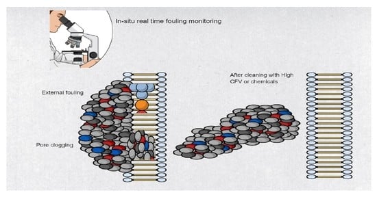
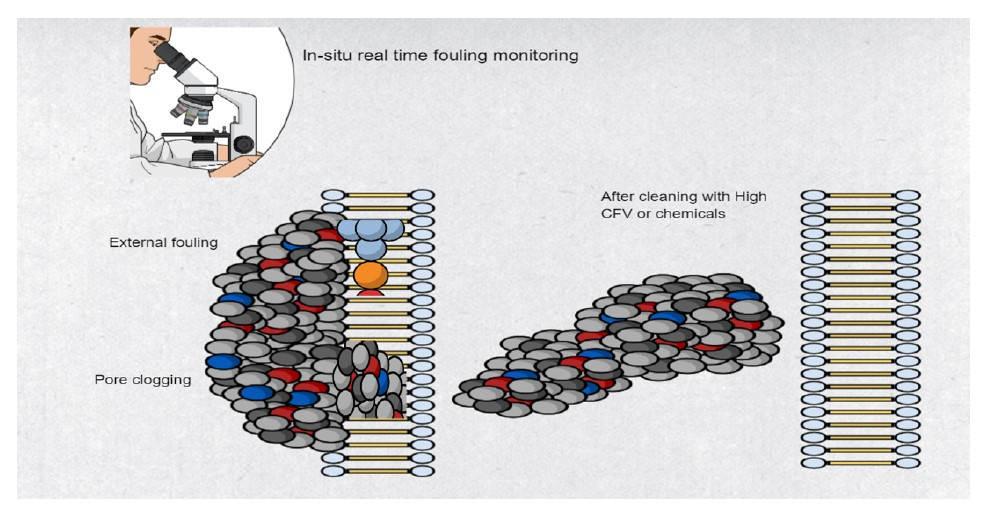
7. In-Situ and Real-Time Fouling Monitoring Techniques

A range of in-situ real-time fouling monitoring techniques can be used to gain a better understanding of the mechanism and fouling layer formation on the FO membrane. These methods include, but are not limited to, direct observation through the membrane (DOTM), ultrasonic time domain reflectometry (UTDR), nuclear magnetic resonance (NMR), optical coherence tomography (OCT), electrical impedance spectroscopy (EIS) and confocal laser scanning microscopy coupled with multiple fluorescent labelling.

7.1. Direct Observation over the Microscope (DOTM)

In forward osmosis, some researchers have used optical microscopy for characterizing fouling of the membrane [62,64]. Direct observation over the membrane (DOTM) is a highly sensitive method to detect fouling deposition on the membrane surface; such small deposition cannot be registered with flux measurement [63]. The first direct microscopic observation to systematically investigate fouling, conducted by Wang et al. [62] using latex particles as model foulants, revealed that foulants usually get trapped in rough surface areas of the membrane, and increasing the draw solution concentration increases foulant deposition on the membrane surface. Microscopic observation also revealed that the FO mode is more resilient to fouling than the PRO mode, and feed spacers enhance initial and critical flux. The use of a feed spacer to enhance flux was also confirmed by another microscopic observation using model microalgae as foulant [63]. However, it was found later by another in-situ monitoring study that while spacers can enhance flux, they can hinder the cleaning process as well [14]. In-situ observations also confirmed that draw solution containing divalent ions promote severe fouling, due to reverse salt flux, and makes fouling reversibility more challenging [63].
Clearly, DOTM is a very sensitive technique, but its use in the FO is restricted to only transparent membranes or cells with transparent sections. Another limitation of DOTM is its inability to quantify surface coverage of membrane in the FO mode, due to the interference from pore structures of the membrane [63].

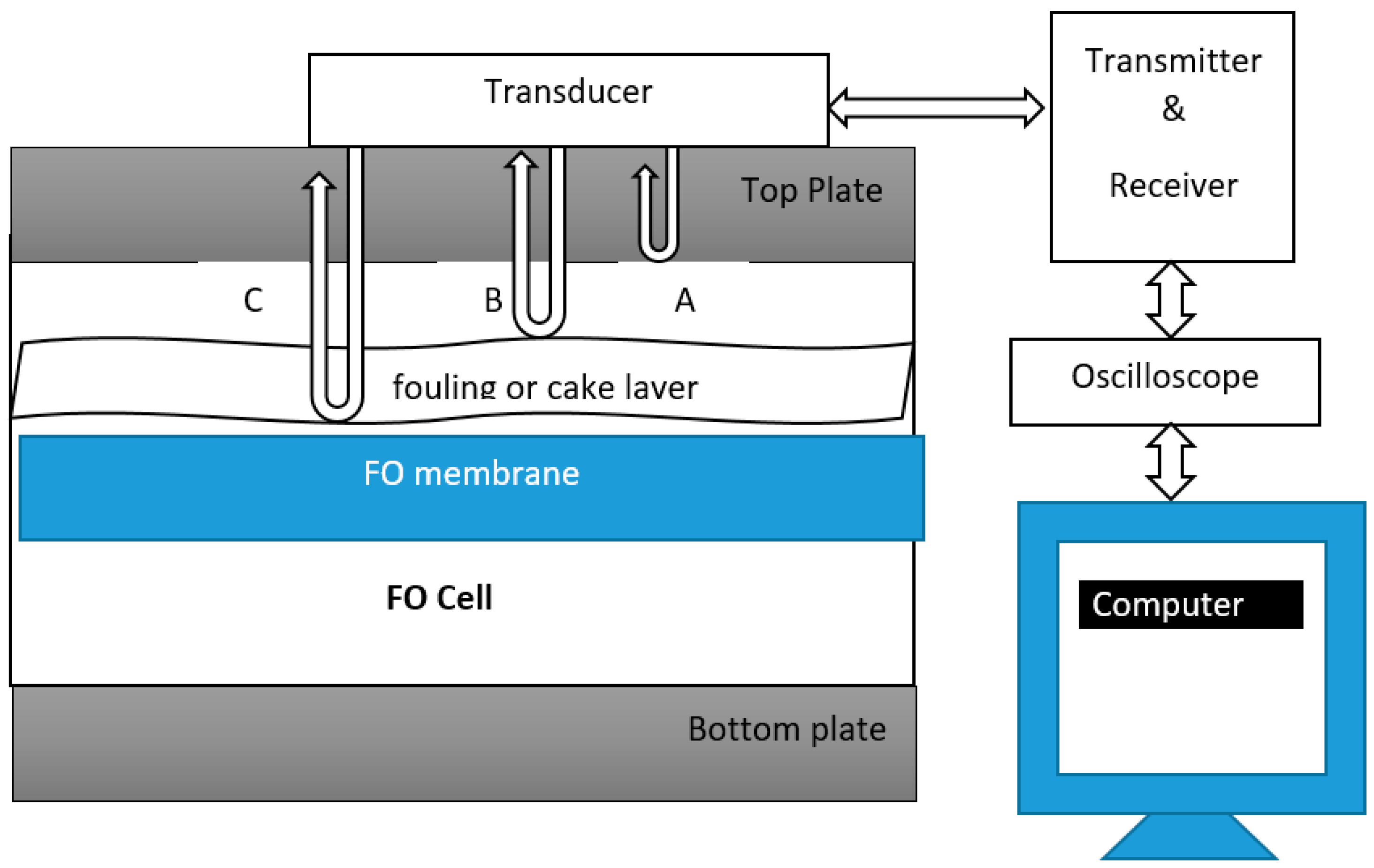
7.2. Ultrasonic Time Domain Reflectometry

Ultrasonic time domain reflectometry (UTDR) is a monitoring technique extensively used in various industrial, medical and military applications [177,178]. UTDR has been used in reverse osmosis to monitor biofouling [179,180]. To the best of our knowledge this technology has not been used in forward osmosis yet. UTDR uses sound waves to determine the location of a moving or stationary interface, and can also provide insights to the physical characteristics of the media through which the sound waves propagates [178]. A possible schematic diagram of UTDR for the FO process is shown below in Figure 5.
An externally mounted transducer (usually water-immersion), which emits and receives ultrasonic signals, is placed in contact with a top plate, as shown in Figure 5. The transducer is usually coupled using commercially available food grade honey to the top plate [178]. The transducer emits ultrasonic waves. There are three interfaces in Figure 5 from which ultrasonic signals are reflected. The top plate and feed solution interface generating echo A, the feed solution and fouling layer interface, generating echo B, and the feed solution and membrane interface, generating echo C. An oscilloscope collects the echo signals. The difference in arrival time represented by ∆T of the echoes is measured. If “c” is the velocity of the ultrasonic wave in the fouling layer, the thickness of the fouling layer ∆S can be calculated by using the following equation.
Δ S = 0.5 c Δ T
Once fouling initiates on the membrane, the acoustic impedance of each interface will change, resulting in the change in the amplitudes of the echoes [178]. A change in thickness of the fouling layer will generate a new echo from the feed solution–fouling layer interface. Similarly, the echo signal will disappear once the membrane is cleaned and the fouling layer diminishes; therefore, UTDR can be a successful and effective technique to assess the effectiveness of cleaning protocols for fouling mitigation as well [182].
The UTDR technique can effectively give us useful insights to monitor fouling layer initiation, fouling layer growth and its removal from the membrane [182]. The limitation of UTDR is that fouling monitoring results may not be precise, due to the slight difference in acoustic properties between the interfaces (feed solution–membrane or feed solution–fouling layer) [179].

7.3. Nuclear Magnetic Resonance or Magnetic Resonance Imaging

Nuclear magnetic resonance (NMR) or magnetic resonance imaging (MRI) can give us insights into biofilm distribution, impact of hydrodynamics and impact of fouling on mass transport [180]. Information about the basic principles of this technology can be found elsewhere [183]. NMR has several advantages, such as being non-invasive, the absence of ionizing radiations, freedom to generate a 3D sample of the image as a whole and image non-metallic samples, which are optically opaque [184]. NMR application was used for the first time by Graf von der Schulenburg et al. [180] to monitor biofouling in spiral wound RO membranes. NMR is also considered a powerful tool for monitoring and analysing biofouling, spatial distribution of the biofilm and the impact of flow on hydrodynamics [185]. Unfortunately, not much literature is available on the application of NMR for fouling studies. This may be due to the fact that NMR is a very expensive technique (Table 5), is limited in availability and requires experienced operators to operate [184]. A low cost, mobile solution has also been reported, through which measurements are conducted using the Earth’s magnetic field as an external magnetic field [186].

7.4. Silent AlarmTM Technology

The Silent AlarmTM technology was designed as an early warning system for membrane fouling and to monitor the performance of the RO plant in real time [187]. This would allow RO plant operators to take immediate measures against fouling. This technology is also capable of quantitatively measuring fouling via a parameter known as Fouling Monitora (FM). For instance, the FM value of 0%–5% means that no fouling is occurring on the membrane, whereas FM value of over 20% suggests that extensive irreversible fouling is occurring and membranes may require replacement. This technology; however, is not able to tell the specific type of fouling on the membrane and thus development of an effective strategy for specific types of fouling control is limited [33]. Until now, this technology has only been applied to study fouling in RO only.

7.5. Feed Fouling Monitor Coupled with UTDR

Developed by Taheri and co-workers [188,189], the feed fouling monitor (FFM) is an online flow simulator that gives us useful insights to the fouling propensity of the feed water. The predicted fouling trends for RO based on FFM alone ignore the effects of CEOP on fouling, and are found to be slower than actual fouling profiles [190]. To incorporate the effects of CEOP, Taheri et al. [189] coupled FFM with UTDR to estimate RO fouling over a range of applied fluxes, using model silica as colloidal foulant. A UF membrane was used for test, as UF membranes are more sensitive to fouling than RO membranes and; therefore, provided increased accuracy. FFM was used to estimate the fouling resistance and porosity of the cake layer, whereas UTDR was incorporated to measure the thickness of the developing fouling layer. This model provided good estimates; however, it can be only applied to colloidal foulant, since measuring the thickness of the organic layer is still a challenge for UTDR [190].

7.6. Optical Coherence Tomography (OCT)

Optical coherence tomography (OCT) is a relatively new and advanced monitoring technique [190], and has been used for monitoring real-time fouling in NF/RO membranes. OCT has several advantages, such as high resolution (eight times higher than SEM), it does not need any signal enhancers or staining of samples and has been used for monitoring fouling in low pressure processes [191]. Since it does not require any staining of a sample, OCT can be a very efficient tool for in-situ and early detection of biofilm development on membranes [190,192]. Recent advances in OCT has made it a very effective technique for assessing the effects of operating conditions and spacer design on membrane fouling [190].

7.7. Electrical Impedance Spectroscopy

A more efficient technology known as electrical impedance spectroscopy can be used for fouling monitoring in the FO process. EIS was, for the first time, employed by Kavanagh et al. [193] to monitor fouling in RO. Since that time, it has been used successfully in various RO studies for fouling monitoring [194,195,196]. The potential of EIS to detect inorganic fouling in an osmotically-driven flow chamber has also been demonstrated [197]. The biggest advantage of EIS is its sensitivity to very small changes that occurs on the membrane surface (measurements at low frequencies are recommended) and the capability to detect the type of fouling [198]. The impedance spectra obtained from different types of foulants varies, and can give an indication to the type of fouling [198]. Monitoring fouling with EIS in the FO process can be useful research in the future.

7.8. Confocal Laser Scanning Microscopy Coupled with Multiple Flouresence Labelling

One of the best approaches for in-situ real-time fouling monitoring is coupling confocal laser scanning microscopy (CLSM) with multiple fluorescence labelling [30]. This technique can give us insight into the structure, distribution and function of biofilm constituents on a microscale [162]. However, CLSM has some limitations, such as high brightness (which can cause photo-damage to the specimen), fluorescence saturation and the use of a monochromatic laser [199].

8. Conclusions

We conclude that, despite a surge in the number of publications on FO, very few papers discuss fouling with real wastewater. We believe that further research is needed to investigate fouling in more detail using real wastewater or seawater feeds. The number of papers discussing critical flux in forward osmosis is approximately less than 20 since 2010. We conclude the following from this review:
  • Fouling in FO is reversible, mostly, and flux can be restored using high cross flow or improved hydrodynamics; however, it can be irreversible as well (e.g., biofouling) and chemical cleaning is then required.
  • Most fouling studies use model foulants in fouling studies, such as alginate, BSA, humic acid and silica particles. This may cause confusion whether the same results will be translated for seawater or wastewater feeds.
  • Novel antifouling membranes can enhance FO efficiency; however, commercial products may take a long time to develop. Most lab-fabricated antifouling membranes have very intricate synthesis processes and use expensive nanomaterials.
  • In-situ real-time fouling monitoring is an urgent need for FO advancements and to mitigate fouling. In-situ cleaning can be done in correspondence with when fouling occurs, and this will improve efficiency. A very few publications on real-time monitoring of FO membrane fouling using state of the art technologies are available.

Author Contributions

Conceptualization, I.I., A.A. (Ali Altaee), O.N.; writing—original draft preparation, I.I., A.A. (Ali Altaee); writing—review A.S., A.A. (Alaa Alhawari), A.M., A.A.A.; supervision, A.A. (Ali Altaee), A.S., A.A. (Alaa Alhawari).

Funding

This publication was made possible by NPRP grant 10-0117-170176 from the Qatar National Research Fund (A member of Qatar Foundation).

Acknowledgments

The authors would like to sincerely thank the two anonymous reviewers of the journal for critically reading the manuscript and suggesting substantial improvements.

Conflicts of Interest

The authors declare no conflict of interest.

References

  1. Lutchmiah, K.; Verliefde, A.R.; Roest, K.; Rietveld, L.C.; Cornelissen, E.R. Forward osmosis for application in wastewater treatment: A review. Water Res. 2014, 58, 179–197. [Google Scholar] [CrossRef] [PubMed]
  2. Roorda, J.H. Filtration Characteristics in Dead-End Ultrafiltration of Wwtp-Effluent; TU Delft, Delft University of Technology: Delft, The Netherlands, 2004. [Google Scholar]
  3. She, Q.; Wang, R.; Fane, A.G.; Tang, C.Y. Membrane fouling in osmotically driven membrane processes: A review. J. Membr. Sci. 2016, 499, 201–233. [Google Scholar] [CrossRef]
  4. Chun, Y.; Mulcahy, D.; Zou, L.; Kim, I.S. A Short Review of Membrane Fouling in Forward Osmosis Processes. Membranes (Basel) 2017, 7, 30. [Google Scholar] [CrossRef] [PubMed]
  5. Mondal, S.; Field, R.W.; Wu, J.J. Novel approach for sizing forward osmosis membrane systems. J. Membr. Sci. 2017, 541, 321–328. [Google Scholar] [CrossRef]
  6. Zhao, P.; Gao, B.; Yue, Q.; Liu, P.; Shon, H.K. Fatty acid fouling of forward osmosis membrane: Effects of pH, calcium, membrane orientation, initial permeate flux and foulant composition. J. Environ. Sci. 2016, 46, 55–62. [Google Scholar] [CrossRef] [PubMed]
  7. Korenak, J.; Basu, S.; Balakrishnan, M.; Hélix-Nielsen, C.; Petrinic, I. Forward Osmosis in Wastewater Treatment Processes. Acta Chim. Slov. 2017, 83–94. [Google Scholar] [CrossRef]
  8. Arkhangelsky, E.; Wicaksana, F.; Chou, S.; Al-Rabiah, A.A.; Al-Zahrani, S.M.; Wang, R. Effects of scaling and cleaning on the performance of forward osmosis hollow fiber membranes. J. Membr. Sci. 2012, 415–416, 101–108. [Google Scholar] [CrossRef]
  9. Jiang, S.; Li, Y.; Ladewig, B.P. A review of reverse osmosis membrane fouling and control strategies. Sci. Total Environ. 2017, 595, 567–583. [Google Scholar] [CrossRef]
  10. Hoek, E.M.V.; Elimelech, M. Cake-Enhanced Concentration Polarization:  A New Fouling Mechanism for Salt-Rejecting Membranes. Environ. Sci. Technol. 2003, 37, 5581–5588. [Google Scholar] [CrossRef]
  11. Siddiqui, F.A.; She, Q.; Fane, A.G.; Field, R.W. Exploring the differences between forward osmosis and reverse osmosis fouling. J. Membr. Sci. 2018, 565, 241–253. [Google Scholar] [CrossRef]
  12. She, Q.; Hou, D.; Liu, J.; Tan, K.H.; Tang, C.Y. Effect of feed spacer induced membrane deformation on the performance of pressure retarded osmosis (PRO): Implications for PRO process operation. J. Membr. Sci. 2013, 445, 170–182. [Google Scholar] [CrossRef]
  13. Nagy, E.; Hegedüs, I.; Tow, E.W.; Lienhard, V.J.H. Effect of fouling on performance of pressure retarded osmosis (PRO) and forward osmosis (FO). J. Membr. Sci. 2018, 565, 450–462. [Google Scholar] [CrossRef]
  14. Tow, E.W.; Rencken, M.M.; Lienhard, J.H. In situ visualization of organic fouling and cleaning mechanisms in reverse osmosis and forward osmosis. Desalination 2016, 399, 138–147. [Google Scholar] [CrossRef]
  15. Gorzalski, A.S.; Coronell, O. Fouling of nanofiltration membranes in full- and bench-scale systems treating groundwater containing silica. J. Membr. Sci. 2014, 468, 349–359. [Google Scholar] [CrossRef]
  16. Bogler, A.; Lin, S.; Bar-Zeev, E. Biofouling of membrane distillation, forward osmosis and pressure retarded osmosis: Principles, impacts and future directions. J. Membr. Sci. 2017, 542, 378–398. [Google Scholar] [CrossRef]
  17. Bucs, S.S.; Valladares Linares, R.; Vrouwenvelder, J.S.; Picioreanu, C. Biofouling in forward osmosis systems: An experimental and numerical study. Water Res. 2016, 106, 86–97. [Google Scholar] [CrossRef]
  18. Vrouwenvelder, J.S.; Manolarakis, S.A.; van der Hoek, J.P.; van Paassen, J.A.M.; van der Meer, W.G.J.; van Agtmaal, J.M.C.; Prummel, H.D.M.; Kruithof, J.C.; van Loosdrecht, M.C.M. Quantitative biofouling diagnosis in full scale nanofiltration and reverse osmosis installations. Water Res. 2008, 42, 4856–4868. [Google Scholar] [CrossRef]
  19. Shannon, M.A.; Bohn, P.W.; Elimelech, M.; Georgiadis, J.G.; Mariñas, B.J.; Mayes, A.M. Science and technology for water purification in the coming decades. Nature 2008, 452, 301–310. [Google Scholar] [CrossRef]
  20. O’Toole, G.; Kaplan, H.B.; Kolter, R. Biofilm formation as microbial development. Annu. Rev. Microbiol. 2000, 54, 49–79. [Google Scholar] [CrossRef]
  21. Abid, H.S.; Johnson, D.J.; Hashaikeh, R.; Hilal, N. A review of efforts to reduce membrane fouling by control of feed spacer characteristics. Desalination 2017, 420, 384–402. [Google Scholar] [CrossRef]
  22. Hausman, R.; Gullinkala, T.; Escobar, I.C. Development of low-biofouling polypropylene feedspacers for reverse osmosis. J. Appl. Polym. Sci. 2009, 114, 3068–3073. [Google Scholar] [CrossRef]
  23. Goulter, R.M.; Gentle, I.R.; Dykes, G.A. Issues in determining factors influencing bacterial attachment: A review using the attachment of Escherichia coli to abiotic surfaces as an example. Lett. Appl. Microbiol. 2009, 49, 1–7. [Google Scholar] [CrossRef] [PubMed]
  24. Cornel, P.K.; Summers, R.S.; Roberts, P.V. Diffusion of humic acid in dilute aqueous solution. J. Colloid Interface Sci. 1986, 110, 149–164. [Google Scholar] [CrossRef]
  25. Valladares Linares, R.; Li, Z.; Sarp, S.; Bucs, S.S.; Amy, G.; Vrouwenvelder, J.S. Forward osmosis niches in seawater desalination and wastewater reuse. Water Res 2014, 66, 122–139. [Google Scholar] [CrossRef]
  26. Lee, S.; Boo, C.; Elimelech, M.; Hong, S. Comparison of fouling behavior in forward osmosis (FO) and reverse osmosis (RO). J. Membr. Sci. 2010, 365, 34–39. [Google Scholar] [CrossRef]
  27. Li, Z.-Y.; Yangali-Quintanilla, V.; Valladares-Linares, R.; Li, Q.; Zhan, T.; Amy, G. Flux patterns and membrane fouling propensity during desalination of seawater by forward osmosis. Water Res. 2012, 46, 195–204. [Google Scholar] [CrossRef]
  28. Myint, A.A.; Lee, W.; Mun, S.; Ahn, C.H.; Lee, S.; Yoon, J. Influence of membrane surface properties on the behavior of initial bacterial adhesion and biofilm development onto nanofiltration membranes. Biofouling 2010, 26, 313–321. [Google Scholar] [CrossRef]
  29. Yoon, H.; Baek, Y.; Yu, J.; Yoon, J. Biofouling occurrence process and its control in the forward osmosis. Desalination 2013, 325, 30–36. [Google Scholar] [CrossRef]
  30. Mi, B.; Elimelech, M. Organic fouling of forward osmosis membranes: Fouling reversibility and cleaning without chemical reagents. J. Membr. Sci. 2010, 348, 337–345. [Google Scholar] [CrossRef]
  31. An, Y.H.; Friedman, R.J. Concise review of mechanisms of bacterial adhesion to biomaterial surfaces. J. Biomed. Mater. Res. 1998, 43, 338–348. [Google Scholar] [CrossRef]
  32. Gu, Y.; Wang, Y.-N.; Wei, J.; Tang, C.Y. Organic fouling of thin-film composite polyamide and cellulose triacetate forward osmosis membranes by oppositely charged macromolecules. Water Res. 2013, 47, 1867–1874. [Google Scholar] [CrossRef] [PubMed]
  33. Nguyen, T.; Roddick, F.A.; Fan, L. Biofouling of Water Treatment Membranes: A Review of the Underlying Causes, Monitoring Techniques and Control Measures. Membranes 2012, 2, 804–840. [Google Scholar] [CrossRef]
  34. Amy, G. Fundamental understanding of organic matter fouling of membranes. Desalination 2008, 231, 44–51. [Google Scholar] [CrossRef]
  35. Parida, V.; Ng, H.Y. Forward osmosis organic fouling: Effects of organic loading, calcium and membrane orientation. Desalination 2013, 312, 88–98. [Google Scholar] [CrossRef]
  36. Combe, C.; Molis, E.; Lucas, P.; Riley, R.; Clark, M.M. The effect of CA membrane properties on adsorptive fouling by humic acid. J. Membr. Sci. 1999, 154, 73–87. [Google Scholar] [CrossRef]
  37. Jones, K.L.; O’Melia, C.R. Protein and humic acid adsorption onto hydrophilic membrane surfaces: Effects of pH and ionic strength. J. Membr. Sci. 2000, 165, 31–46. [Google Scholar] [CrossRef]
  38. Yuan, W.; Zydney, A.L. Humic acid fouling during microfiltration. J. Membr. Sci. 1999, 157, 1–12. [Google Scholar] [CrossRef]
  39. Shon, H.K.; Vigneswaran, S.; Kim, I.S.; Cho, J.; Ngo, H.H. Fouling of ultrafiltration membrane by effluent organic matter: A detailed characterization using different organic fractions in wastewater. J. Membr. Sci. 2006, 278, 232–238. [Google Scholar] [CrossRef]
  40. Xie, M.; Nghiem, L.D.; Price, W.E.; Elimelech, M. Impact of humic acid fouling on membrane performance and transport of pharmaceutically active compounds in forward osmosis. Water Res. 2013, 47, 4567–4575. [Google Scholar] [CrossRef]
  41. Jarusutthirak, C.; Amy, G.; Croué, J.-P. Fouling characteristics of wastewater effluent organic matter (EfOM) isolates on NF and UF membranes. Desalination 2002, 145, 247–255. [Google Scholar] [CrossRef]
  42. Fan, L.; Harris, J.L.; Roddick, F.A.; Booker, N.A. Influence of the characteristics of natural organic matter on the fouling of microfiltration membranes. Water Res. 2001, 35, 4455–4463. [Google Scholar] [CrossRef]
  43. Mi, B.; Elimelech, M. Chemical and physical aspects of organic fouling of forward osmosis membranes. J. Membr. Sci. 2008, 320, 292–302. [Google Scholar] [CrossRef]
  44. Fane, T. Inorganic Scaling. In Encyclopedia of Membranes; Drioli, E., Giorno, L., Eds.; Springer: Berlin/Heidelberg, Germany, 2016; pp. 1–2. [Google Scholar]
  45. Mi, B.; Elimelech, M. Silica scaling and scaling reversibility in forward osmosis. Desalination 2013, 312, 75–81. [Google Scholar] [CrossRef]
  46. Xie, M.; Gray, S.R. Silica scaling in forward osmosis: From solution to membrane interface. Water Res. 2017, 108, 232–239. [Google Scholar] [CrossRef]
  47. Lee, S.; Kim, Y.C. Calcium carbonate scaling by reverse draw solute diffusion in a forward osmosis membrane for shale gas wastewater treatment. J. Membr. Sci. 2017, 522, 257–266. [Google Scholar] [CrossRef]
  48. Zhang, M.; Shan, J.; Tang, C.Y. Gypsum scaling during forward osmosis process—A direct microscopic observation study. Desalin. Water Treat. 2016, 57, 3317–3327. [Google Scholar] [CrossRef]
  49. Mi, B.; Elimelech, M. Gypsum Scaling and Cleaning in Forward Osmosis: Measurements and Mechanisms. Environ. Sci. Technol. 2010, 44, 2022–2028. [Google Scholar] [CrossRef]
  50. Choi, Y.-J.; Kim, S.-H.; Jeong, S.; Hwang, T.-M. Application of ultrasound to mitigate calcium sulfate scaling and colloidal fouling. Desalination 2014, 336, 153–159. [Google Scholar] [CrossRef]
  51. Bush, J.A.; Vanneste, J.; Gustafson, E.M.; Waechter, C.A.; Jassby, D.; Turchi, C.S.; Cath, T.Y. Prevention and management of silica scaling in membrane distillation using pH adjustment. J. Membr. Sci. 2018, 554, 366–377. [Google Scholar] [CrossRef]
  52. Brück, A.; McCoy, L.L.; Kilway, K.V. Hydrogen Bonds in Carboxylic Acid−Carboxylate Systems in Solution. 1. In Anhydrous, Aprotic Media. Org. Lett. 2000, 2, 2007–2009. [Google Scholar] [CrossRef]
  53. Xie, M.; Gray, S.R. Gypsum scaling in forward osmosis: Role of membrane surface chemistry. J. Membr. Sci. 2016, 513, 250–259. [Google Scholar] [CrossRef]
  54. Hatziantoniou, D.; Howell, J.A. Influence of the properties and characteristics of sugar-beet pulp extract on its fouling and rejection behaviour during membrane filtration. Desalination 2002, 148, 67–72. [Google Scholar] [CrossRef]
  55. Lee, S.; Elimelech, M. Relating Organic Fouling of Reverse Osmosis Membranes to Intermolecular Adhesion Forces. Environ. Sci. Technol. 2006, 40, 980–987. [Google Scholar] [CrossRef] [PubMed]
  56. Singh, G.; Song, L. Experimental correlations of pH and ionic strength effects on the colloidal fouling potential of silica nanoparticles in crossflow ultrafiltration. J. Membr. Sci. 2007, 303, 112–118. [Google Scholar] [CrossRef]
  57. Brunelle, M.T. Colloidal fouling of reverse osmosis membranes. Desalination 1980, 32, 127–135. [Google Scholar] [CrossRef]
  58. Boo, C.; Lee, S.; Elimelech, M.; Meng, Z.; Hong, S. Colloidal fouling in forward osmosis: Role of reverse salt diffusion. J. Membr. Sci. 2012, 390–391, 277–284. [Google Scholar] [CrossRef]
  59. Zou, S.; Gu, Y.; Xiao, D.; Tang, C.Y. The role of physical and chemical parameters on forward osmosis membrane fouling during algae separation. J. Membr. Sci. 2011, 366, 356–362. [Google Scholar] [CrossRef]
  60. Espinasse, B.; Bacchin, P.; Aimar, P. On an experimental method to measure critical flux in ultrafiltration. Desalination 2002, 146, 91–96. [Google Scholar] [CrossRef]
  61. Bacchin, P.; Aimar, P.; Field, R.W. Critical and sustainable fluxes: Theory, experiments and applications. J. Membr. Sci. 2006, 281, 42–69. [Google Scholar] [CrossRef]
  62. Wang, Y.; Wicaksana, F.; Tang, C.Y.; Fane, A.G. Direct Microscopic Observation of Forward Osmosis Membrane Fouling. Environ. Sci. Technol. 2010, 44, 7102–7109. [Google Scholar] [CrossRef]
  63. Zou, S.; Wang, Y.-N.; Wicaksana, F.; Aung, T.; Wong, P.C.Y.; Fane, A.G.; Tang, C.Y. Direct microscopic observation of forward osmosis membrane fouling by microalgae: Critical flux and the role of operational conditions. J. Membr. Sci. 2013, 436, 174–185. [Google Scholar] [CrossRef]
  64. Liu, Y.; Mi, B. Combined fouling of forward osmosis membranes: Synergistic foulant interaction and direct observation of fouling layer formation. J. Membr. Sci. 2012, 407–408, 136–144. [Google Scholar] [CrossRef]
  65. Zhao, S.; Zou, L.; Mulcahy, D. Effects of membrane orientation on process performance in forward osmosis applications. J. Membr. Sci. 2011, 382, 308–315. [Google Scholar] [CrossRef]
  66. Park, M.J.; Gonzales, R.R.; Abdel-Wahab, A.; Phuntsho, S.; Shon, H.K. Hydrophilic polyvinyl alcohol coating on hydrophobic electrospun nanofiber membrane for high performance thin film composite forward osmosis membrane. Desalination 2018, 426, 50–59. [Google Scholar] [CrossRef]
  67. Kumar, R.; Ismail, A.F. Fouling control on microfiltration/ultrafiltration membranes: Effects of morphology, hydrophilicity, and charge. J. Appl. Polym. Sci. 2015, 132. [Google Scholar] [CrossRef]
  68. Yu, Y.; Seo, S.; Kim, I.-C.; Lee, S. Nanoporous polyethersulfone (PES) membrane with enhanced flux applied in forward osmosis process. J. Membr. Sci. 2011, 375, 63–68. [Google Scholar] [CrossRef]
  69. Emadzadeh, D.; Lau, W.J.; Matsuura, T.; Rahbari-Sisakht, M.; Ismail, A.F. A novel thin film composite forward osmosis membrane prepared from PSf–TiO2 nanocomposite substrate for water desalination. Chem. Eng. J. 2014, 237, 70–80. [Google Scholar] [CrossRef]
  70. Setiawan, L.; Wang, R.; Li, K.; Fane, A.G. Fabrication of novel poly(amide–imide) forward osmosis hollow fiber membranes with a positively charged nanofiltration-like selective layer. J. Membr. Sci. 2011, 369, 196–205. [Google Scholar] [CrossRef]
  71. Chiao, Y.-H.; Sengupta, A.; Chen, S.-T.; Huang, S.-H.; Hu, C.-C.; Hung, W.-S.; Chang, Y.; Qian, X.; Wickramasinghe, S.R.; Lee, K.-R.; et al. Zwitterion augmented polyamide membrane for improved forward osmosis performance with significant antifouling characteristics. Sep. Purif. Technol. 2019, 212, 316–325. [Google Scholar] [CrossRef]
  72. Choi, H.-G.; Shah, A.A.; Nam, S.-E.; Park, Y.-I.; Park, H. Thin-film composite membranes comprising ultrathin hydrophilic polydopamine interlayer with graphene oxide for forward osmosis. Desalination 2019, 449, 41–49. [Google Scholar] [CrossRef]
  73. Ni, T.; Ge, Q. Highly hydrophilic thin-film composition forward osmosis (FO) membranes functionalized with aniline sulfonate/bisulfonate for desalination. J. Membr. Sci. 2018, 564, 732–741. [Google Scholar] [CrossRef]
  74. Shakeri, A.; Salehi, H.; Ghorbani, F.; Amini, M.; Naslhajian, H. Polyoxometalate based thin film nanocomposite forward osmosis membrane: Superhydrophilic, anti-fouling, and high water permeable. J. Colloid Interface Sci. 2019, 536, 328–338. [Google Scholar] [CrossRef] [PubMed]
  75. Chun, Y.; Qing, L.; Sun, G.; Bilad, M.R.; Fane, A.G.; Chong, T.H. Prototype aquaporin-based forward osmosis membrane: Filtration properties and fouling resistance. Desalination 2018, 445, 75–84. [Google Scholar] [CrossRef]
  76. Rastgar, M.; Bozorg, A.; Shakeri, A.; Sadrzadeh, M. Substantially improved antifouling properties in electro-oxidative graphene laminate forward osmosis membrane. Chem. Eng. Res. Des. 2019, 141, 413–424. [Google Scholar] [CrossRef]
  77. Bao, X.; Wu, Q.; Shi, W.; Wang, W.; Yu, H.; Zhu, Z.; Zhang, X.; Zhang, Z.; Zhang, R.; Cui, F. Polyamidoamine dendrimer grafted forward osmosis membrane with superior ammonia selectivity and robust antifouling capacity for domestic wastewater concentration. Water Res. 2019, 153, 1–10. [Google Scholar] [CrossRef]
  78. Shakeri, A.; Salehi, H.; Rastgar, M. Chitosan-based thin active layer membrane for forward osmosis desalination. Carbohydr. Polym. 2017, 174, 658–668. [Google Scholar] [CrossRef]
  79. Li, M.-N.; Sun, X.-F.; Wang, L.; Wang, S.-Y.; Afzal, M.Z.; Song, C.; Wang, S.-G. Forward osmosis membranes modified with laminar MoS2 nanosheet to improve desalination performance and antifouling properties. Desalination 2018, 436, 107–113. [Google Scholar] [CrossRef]
  80. Qiu, M.; He, C. Novel zwitterion-silver nanocomposite modified thin-film composite forward osmosis membrane with simultaneous improved water flux and biofouling resistance property. Appl. Surf. Sci. 2018, 455, 492–501. [Google Scholar] [CrossRef]
  81. Zuo, H.-R.; Fu, J.-B.; Cao, G.-P.; Hu, N.; Lu, H.; Liu, H.-Q.; Chen, P.-P.; Yu, J. The effects of surface-charged submicron polystyrene particles on the structure and performance of PSF forward osmosis membrane. Appl. Surf. Sci. 2018, 436, 1181–1192. [Google Scholar] [CrossRef]
  82. Guo, H.; Yao, Z.; Wang, J.; Yang, Z.; Ma, X.; Tang, C.Y. Polydopamine coating on a thin film composite forward osmosis membrane for enhanced mass transport and antifouling performance. J. Membr. Sci. 2018, 551, 234–242. [Google Scholar] [CrossRef]
  83. Xu, W.; Ge, Q. Novel functionalized forward osmosis (FO) membranes for FO desalination: Improved process performance and fouling resistance. J. Membr. Sci. 2018, 555, 507–516. [Google Scholar] [CrossRef]
  84. Han, G.; Chung, T.-S.; Toriida, M.; Tamai, S. Thin-film composite forward osmosis membranes with novel hydrophilic supports for desalination. J. Membr. Sci. 2012, 423–424, 543–555. [Google Scholar] [CrossRef]
  85. Yip, N.Y.; Tiraferri, A.; Phillip, W.A.; Schiffman, J.D.; Elimelech, M. High Performance Thin-Film Composite Forward Osmosis Membrane. Environ. Sci. Technol. 2010, 44, 3812–3818. [Google Scholar] [CrossRef] [PubMed]
  86. Widjojo, N.; Chung, T.-S.; Weber, M.; Maletzko, C.; Warzelhan, V. The role of sulphonated polymer and macrovoid-free structure in the support layer for thin-film composite (TFC) forward osmosis (FO) membranes. J. Membr. Sci. 2011, 383, 214–223. [Google Scholar] [CrossRef]
  87. Tiraferri, A.; Yip, N.Y.; Phillip, W.A.; Schiffman, J.D.; Elimelech, M. Relating performance of thin-film composite forward osmosis membranes to support layer formation and structure. J. Membr. Sci. 2011, 367, 340–352. [Google Scholar] [CrossRef]
  88. Lay, W.C.L.; Zhang, J.; Tang, C.; Wang, R.; Liu, Y.; Fane, A.G. Factors affecting flux performance of forward osmosis systems. J. Membr. Sci. 2012, 394–395, 151–168. [Google Scholar] [CrossRef]
  89. McCutcheon, J.R.; Elimelech, M. Influence of concentrative and dilutive internal concentration polarization on flux behavior in forward osmosis. J. Membr. Sci. 2006, 284, 237–247. [Google Scholar] [CrossRef]
  90. Cath, T.; Childress, A.; Elimelech, M. Forward osmosis: Principles, applications, and recent developments. J. Membr. Sci. 2006, 281, 70–87. [Google Scholar] [CrossRef]
  91. McCutcheon, J.R.; McGinnis, R.L.; Elimelech, M. Desalination by ammonia–carbon dioxide forward osmosis: Influence of draw and feed solution concentrations on process performance. J. Membr. Sci. 2006, 278, 114–123. [Google Scholar] [CrossRef]
  92. Wang, Y.; Zhang, M.; Liu, Y.; Xiao, Q.; Xu, S. Quantitative evaluation of concentration polarization under different operating conditions for forward osmosis process. Desalination 2016, 398, 106–113. [Google Scholar] [CrossRef]
  93. Kragl, U. Basic Principles of Membrane Technology. (2. Aufl.) Von M. Mulder. Kluwer Academic Publishers, Dordrecht, 1996. 564 S., geb. 174.00 £.—ISBN 0–7923–4247-X. Angew. Chem. 1997, 109, 1420–1421. [Google Scholar] [CrossRef]
  94. Gruber, M.F.; Johnson, C.J.; Tang, C.Y.; Jensen, M.H.; Yde, L.; Hélix-Nielsen, C. Computational fluid dynamics simulations of flow and concentration polarization in forward osmosis membrane systems. J. Membr. Sci. 2011, 379, 488–495. [Google Scholar] [CrossRef]
  95. Zhang, H.; Cheng, S.; Yang, F. Use of a spacer to mitigate concentration polarization during forward osmosis process. Desalination 2014, 347, 112–119. [Google Scholar] [CrossRef]
  96. Gray, G.T.; McCutcheon, J.R.; Elimelech, M. Internal concentration polarization in forward osmosis: Role of membrane orientation. Desalination 2006, 197, 1–8. [Google Scholar] [CrossRef]
  97. Choi, Y.; Hwang, T.M.; Jeong, S.; Lee, S. The use of ultrasound to reduce internal concentration polarization in forward osmosis. Ultrason. Sonochem. 2018, 41, 475–483. [Google Scholar] [CrossRef]
  98. Heikkinen, J.; Kyllönen, H.; Järvelä, E.; Grönroos, A.; Tang, C.Y. Ultrasound-assisted forward osmosis for mitigating internal concentration polarization. J. Membr. Sci. 2017, 528, 147–154. [Google Scholar] [CrossRef]
  99. Wang, Y.; Duan, W.; Wang, W.; Di, W.; Liu, Y.; Liu, Y.; Li, Z.; Hu, H.; Lin, H.; Cui, C.; et al. scAAV9-VEGF prolongs the survival of transgenic ALS mice by promoting activation of M2 microglia and the PI3K/Akt pathway. Brain Res. 2016, 1648, 1–10. [Google Scholar] [CrossRef]
  100. Xie, M.; Tang, C.Y.; Gray, S.R. Spacer-induced forward osmosis membrane integrity loss during gypsum scaling. Desalination 2016, 392, 85–90. [Google Scholar] [CrossRef]
  101. She, Q.; Jin, X.; Tang, C.Y. Osmotic power production from salinity gradient resource by pressure retarded osmosis: Effects of operating conditions and reverse solute diffusion. J. Membr. Sci. 2012, 401–402, 262–273. [Google Scholar] [CrossRef]
  102. Hawari, A.H.; Kamal, N.; Altaee, A. Combined influence of temperature and flow rate of feeds on the performance of forward osmosis. Desalination 2016, 398, 98–105. [Google Scholar] [CrossRef]
  103. Jung, D.H.; Lee, J.; Kim, D.Y.; Lee, Y.G.; Park, M.; Lee, S.; Yang, D.R.; Kim, J.H. Simulation of forward osmosis membrane process: Effect of membrane orientation and flow direction of feed and draw solutions. Desalination 2011, 277, 83–91. [Google Scholar] [CrossRef]
  104. Wang, K.Y.; Ong, R.C.; Chung, T.-S. Double-Skinned Forward Osmosis Membranes for Reducing Internal Concentration Polarization within the Porous Sublayer. Ind. Eng. Chem. Res. 2010, 49, 4824–4831. [Google Scholar] [CrossRef]
  105. Wei, J.; Qiu, C.; Tang, C.Y.; Wang, R.; Fane, A.G. Synthesis and characterization of flat-sheet thin film composite forward osmosis membranes. J. Membr. Sci. 2011, 372, 292–302. [Google Scholar] [CrossRef]
  106. Song, X.; Liu, Z.; Sun, D.D. Nano Gives the Answer: Breaking the Bottleneck of Internal Concentration Polarization with a Nanofiber Composite Forward Osmosis Membrane for a High Water Production Rate. Adv. Mater. 2011, 23, 3256–3260. [Google Scholar] [CrossRef] [PubMed]
  107. Zhou, Z.; Lee, J.Y.; Chung, T.-S. Thin film composite forward-osmosis membranes with enhanced internal osmotic pressure for internal concentration polarization reduction. Chem. Eng. J. 2014, 249, 236–245. [Google Scholar] [CrossRef]
  108. Liu, X.; Ng, H.Y. Fabrication of layered silica–polysulfone mixed matrix substrate membrane for enhancing performance of thin-film composite forward osmosis membrane. J. Membr. Sci. 2015, 481, 148–163. [Google Scholar] [CrossRef]
  109. Puguan, J.M.C.; Kim, H.-S.; Lee, K.-J.; Kim, H. Low internal concentration polarization in forward osmosis membranes with hydrophilic crosslinked PVA nanofibers as porous support layer. Desalination 2014, 336, 24–31. [Google Scholar] [CrossRef]
  110. Li, M.; Karanikola, V.; Zhang, X.; Wang, L.; Elimelech, M. A Self-Standing, Support-Free Membrane for Forward Osmosis with No Internal Concentration Polarization. Environ. Sci. Technol. Lett. 2018, 5, 266–271. [Google Scholar] [CrossRef]
  111. Gai, J.-G.; Gong, X.-L. Zero internal concentration polarization FO membrane: Functionalized graphene. J. Mater. Chem. A 2014, 2, 425–429. [Google Scholar] [CrossRef]
  112. Phillip, W.A.; Yong, J.S.; Elimelech, M. Reverse Draw Solute Permeation in Forward Osmosis: Modeling and Experiments. Environ. Sci. Technol. 2010, 44, 5170–5176. [Google Scholar] [CrossRef] [PubMed]
  113. Hickenbottom, K.L.; Hancock, N.T.; Hutchings, N.R.; Appleton, E.W.; Beaudry, E.G.; Xu, P.; Cath, T.Y. Forward osmosis treatment of drilling mud and fracturing wastewater from oil and gas operations. Desalination 2013, 312, 60–66. [Google Scholar] [CrossRef]
  114. Zhao, S.; Zou, L.; Tang, C.Y.; Mulcahy, D. Recent developments in forward osmosis: Opportunities and challenges. J. Membr. Sci. 2012, 396, 1–21. [Google Scholar] [CrossRef]
  115. Xie, M.; Bar-Zeev, E.; Hashmi, S.M.; Nghiem, L.D.; Elimelech, M. Role of Reverse Divalent Cation Diffusion in Forward Osmosis Biofouling. Environ. Sci. Technol. 2015, 49, 13222–13229. [Google Scholar] [CrossRef]
  116. Nguyen, N.C.; Chen, S.S.; Jain, S.; Nguyen, H.T.; Ray, S.S.; Ngo, H.H.; Guo, W.; Lam, N.T.; Duong, H.C. Exploration of an innovative draw solution for a forward osmosis-membrane distillation desalination process. Environ. Sci. Pollut. Res. Int. 2018, 25, 5203–5211. [Google Scholar] [CrossRef]
  117. Achilli, A.; Cath, T.Y.; Childress, A.E. Selection of inorganic-based draw solutions for forward osmosis applications. J. Membr. Sci. 2010, 364, 233–241. [Google Scholar] [CrossRef]
  118. Yaroshchuk, A.; Bruening, M.L.; Licón Bernal, E.E. Solution-Diffusion–Electro-Migration model and its uses for analysis of nanofiltration, pressure-retarded osmosis and forward osmosis in multi-ionic solutions. J. Membr. Sci. 2013, 447, 463–476. [Google Scholar] [CrossRef]
  119. Irvine, G.J.; Rajesh, S.; Georgiadis, M.; Phillip, W.A. Ion Selective Permeation Through Cellulose Acetate Membranes in Forward Osmosis. Environ. Sci. Technol. 2013, 47, 13745–13753. [Google Scholar] [CrossRef] [PubMed]
  120. Boo, C.; Khalil, Y.F.; Elimelech, M. Performance evaluation of trimethylamine–carbon dioxide thermolytic draw solution for engineered osmosis. J. Membr. Sci. 2015, 473, 302–309. [Google Scholar] [CrossRef]
  121. Phuntsho, S.; Shon, H.K.; Hong, S.; Lee, S.; Vigneswaran, S. A novel low energy fertilizer driven forward osmosis desalination for direct fertigation: Evaluating the performance of fertilizer draw solutions. J. Membr. Sci. 2011, 375, 172–181. [Google Scholar] [CrossRef]
  122. She, Q.; Jin, X.; Li, Q.; Tang, C.Y. Relating reverse and forward solute diffusion to membrane fouling in osmotically driven membrane processes. Water Res. 2012, 46, 2478–2486. [Google Scholar] [CrossRef] [PubMed]
  123. Zhang, S.; Wang, K.Y.; Chung, T.-S.; Chen, H.; Jean, Y.C.; Amy, G. Well-constructed cellulose acetate membranes for forward osmosis: Minimized internal concentration polarization with an ultra-thin selective layer. J. Membr. Sci. 2010, 360, 522–535. [Google Scholar] [CrossRef]
  124. Blandin, G.; Verliefde, A.R.D.; Tang, C.Y.; Childress, A.E.; Le-Clech, P. Validation of assisted forward osmosis (AFO) process: Impact of hydraulic pressure. J. Membr. Sci. 2013, 447, 1–11. [Google Scholar] [CrossRef]
  125. Tang, C.Y.; She, Q.; Lay, W.C.L.; Wang, R.; Fane, A.G. Coupled effects of internal concentration polarization and fouling on flux behavior of forward osmosis membranes during humic acid filtration. J. Membr. Sci. 2010, 354, 123–133. [Google Scholar] [CrossRef]
  126. Phuntsho, S.; Sahebi, S.; Majeed, T.; Lotfi, F.; Kim, J.E.; Shon, H.K. Assessing the major factors affecting the performances of forward osmosis and its implications on the desalination process. Chem. Eng. J. 2013, 231, 484–496. [Google Scholar] [CrossRef]
  127. Achilli, A.; Cath, T.Y.; Marchand, E.A.; Childress, A.E. The forward osmosis membrane bioreactor: A low fouling alternative to MBR processes. Desalination 2009, 239, 10–21. [Google Scholar] [CrossRef]
  128. Zhang, J.; Loong, W.L.C.; Chou, S.; Tang, C.; Wang, R.; Fane, A.G. Membrane biofouling and scaling in forward osmosis membrane bioreactor. J. Membr. Sci. 2012, 403–404, 8–14. [Google Scholar] [CrossRef]
  129. Sun, Y.; Tian, J.; Zhao, Z.; Shi, W.; Liu, D.; Cui, F. Membrane fouling of forward osmosis (FO) membrane for municipal wastewater treatment: A comparison between direct FO and OMBR. Water Res. 2016, 104, 330–339. [Google Scholar] [CrossRef] [PubMed]
  130. Sun, Y.; Tian, J.; Song, L.; Gao, S.; Shi, W.; Cui, F. Dynamic changes of the fouling layer in forward osmosis based membrane processes for municipal wastewater treatment. J. Membr. Sci. 2018, 549, 523–532. [Google Scholar] [CrossRef]
  131. Cornelissen, E.R.; Harmsen, D.; de Korte, K.F.; Ruiken, C.J.; Qin, J.-J.; Oo, H.; Wessels, L.P. Membrane fouling and process performance of forward osmosis membranes on activated sludge. J. Membr. Sci. 2008, 319, 158–168. [Google Scholar] [CrossRef]
  132. Qiu, G.; Ting, Y.-P. Short-term fouling propensity and flux behavior in an osmotic membrane bioreactor for wastewater treatment. Desalination 2014, 332, 91–99. [Google Scholar] [CrossRef]
  133. Chen, M.-Y.; Lee, D.-J.; Yang, Z.; Peng, X.F.; Lai, J.Y. Fluorecent Staining for Study of Extracellular Polymeric Substances in Membrane Biofouling Layers. Environ. Sci. Technol. 2006, 40, 6642–6646. [Google Scholar] [CrossRef] [PubMed]
  134. Wang, X.; Zhao, Y.; Yuan, B.; Wang, Z.; Li, X.; Ren, Y. Comparison of biofouling mechanisms between cellulose triacetate (CTA) and thin-film composite (TFC) polyamide forward osmosis membranes in osmotic membrane bioreactors. Bioresour. Technol. 2016, 202, 50–58. [Google Scholar] [CrossRef] [PubMed]
  135. Wang, X.; Chang, V.W.C.; Tang, C.Y. Osmotic membrane bioreactor (OMBR) technology for wastewater treatment and reclamation: Advances, challenges, and prospects for the future. J. Membr. Sci. 2016, 504, 113–132. [Google Scholar] [CrossRef]
  136. Yuan, B.; Wang, X.; Tang, C.; Li, X.; Yu, G. In situ observation of the growth of biofouling layer in osmotic membrane bioreactors by multiple fluorescence labeling and confocal laser scanning microscopy. Water Res. 2015, 75, 188–200. [Google Scholar] [CrossRef] [PubMed]
  137. Bell, E.A.; Holloway, R.W.; Cath, T.Y. Evaluation of forward osmosis membrane performance and fouling during long-term osmotic membrane bioreactor study. J. Membr. Sci. 2016, 517, 1–13. [Google Scholar] [CrossRef]
  138. Wang, X.-M.; Li, X.-Y. Accumulation of biopolymer clusters in a submerged membrane bioreactor and its effect on membrane fouling. Water Res. 2008, 42, 855–862. [Google Scholar] [CrossRef] [PubMed]
  139. Jin, X.; Tang, C.Y.; Gu, Y.; She, Q.; Qi, S. Boric Acid Permeation in Forward Osmosis Membrane Processes: Modeling, Experiments, and Implications. Environ. Sci. Technol. 2011, 45, 2323–2330. [Google Scholar] [CrossRef]
  140. Qin, J.J.; Kekre, K.A.; Oo, M.H.; Tao, G.; Lay, C.L.; Lew, C.H.; Cornelissen, E.R.; Ruiken, C.J. Preliminary study of osmotic membrane bioreactor: Effects of draw solution on water flux and air scouring on fouling. Water Sci Technol 2010, 62, 1353–1360. [Google Scholar] [CrossRef]
  141. Luo, W.; Xie, M.; Hai, F.I.; Price, W.E.; Nghiem, L.D. Biodegradation of cellulose triacetate and polyamide forward osmosis membranes in an activated sludge bioreactor: Observations and implications. J. Membr. Sci. 2016, 510, 284–292. [Google Scholar] [CrossRef]
  142. Coday, B.D.; Xu, P.; Beaudry, E.G.; Herron, J.; Lampi, K.; Hancock, N.T.; Cath, T.Y. The sweet spot of forward osmosis: Treatment of produced water, drilling wastewater, and other complex and difficult liquid streams. Desalination 2014, 333, 23–35. [Google Scholar] [CrossRef]
  143. Valladares Linares, R.; Li, Z.; Yangali-Quintanilla, V.; Li, Q.; Amy, G. Cleaning protocol for a FO membrane fouled in wastewater reuse. Desalin. Water Treat. 2013, 51, 4821–4824. [Google Scholar] [CrossRef]
  144. Lv, L.; Xu, J.; Shan, B.; Gao, C. Concentration performance and cleaning strategy for controlling membrane fouling during forward osmosis concentration of actual oily wastewater. J. Membr. Sci. 2017, 523, 15–23. [Google Scholar] [CrossRef]
  145. Kim, C.-M.; Kim, S.-J.; Kim, L.H.; Shin, M.S.; Yu, H.-W.; Kim, I.S. Effects of phosphate limitation in feed water on biofouling in forward osmosis (FO) process. Desalination 2014, 349, 51–59. [Google Scholar] [CrossRef]
  146. Alphenaar, P.A.; Sleyster, R.; De Reuver, P.; Ligthart, G.-J.; Lettinga, G. Phosphorus requirement in high-rate anaerobic wastewater treatment. Water Res. 1993, 27, 749–756. [Google Scholar] [CrossRef]
  147. Lehtola, M.J.; Miettinen, I.T.; Vartiainen, T.; Rantakokko, P.; Hirvonen, A.; Martikainen, P.J. Impact of UV disinfection on microbially available phosphorus, organic carbon, and microbial growth in drinking water. Water Res. 2003, 37, 1064–1070. [Google Scholar] [CrossRef]
  148. Kasahara, S.; Maeda, K.; Ishikawa, M. Influence of phosphorus on biofilm accumulation in drinking water distribution systems. Water Sci. Technol. Water Supply 2004, 4, 389–398. [Google Scholar] [CrossRef]
  149. Karageorgiou, K.; Paschalis, M.; Anastassakis, G.N. Removal of phosphate species from solution by adsorption onto calcite used as natural adsorbent. J. Hazard. Mater. 2007, 139, 447–452. [Google Scholar] [CrossRef] [PubMed]
  150. Pradhan, J.; Das, J.; Das, S.; Thakur, R.S. Adsorption of Phosphate from Aqueous Solution Using Activated Red Mud. J. Colloid Interface Sci. 1998, 204, 169–172. [Google Scholar] [CrossRef]
  151. Li, Y.; Liu, C.; Luan, Z.; Peng, X.; Zhu, C.; Chen, Z.; Zhang, Z.; Fan, J.; Jia, Z. Phosphate removal from aqueous solutions using raw and activated red mud and fly ash. J. Hazard. Mater. 2006, 137, 374–383. [Google Scholar] [CrossRef]
  152. Vasudevan, S.; Sozhan, G.; Ravichandran, S.; Jayaraj, J.; Lakshmi, J.; Sheela, M. Studies on the removal of phosphate from drinking water by electrocoagulation process. Ind. Eng. Chem. Res. 2008, 47, 2018–2023. [Google Scholar] [CrossRef]
  153. Fytianos, K.; Voudrias, E.; Raikos, N. Modelling of phosphorus removal from aqueous and wastewater samples using ferric iron. Environ. Pollut. 1998, 101, 123–130. [Google Scholar] [CrossRef]
  154. Wang, Z.; Tang, J.; Zhu, C.; Dong, Y.; Wang, Q.; Wu, Z. Chemical cleaning protocols for thin film composite (TFC) polyamide forward osmosis membranes used for municipal wastewater treatment. J. Membr. Sci. 2015, 475, 184–192. [Google Scholar] [CrossRef]
  155. Kwan, S.E.; Bar-Zeev, E.; Elimelech, M. Biofouling in forward osmosis and reverse osmosis: Measurements and mechanisms. J. Membr. Sci. 2015, 493, 703–708. [Google Scholar] [CrossRef]
  156. Du, X.; Wang, Y.; Qu, F.; Li, K.; Liu, X.; Wang, Z.; Li, G.; Liang, H. Impact of bubbly flow in feed channel of forward osmosis for wastewater treatment: Flux performance and biofouling. Chem. Eng. J. 2017, 316, 1047–1058. [Google Scholar] [CrossRef]
  157. Li, J.-Y.; Ni, Z.-Y.; Zhou, Z.-Y.; Hu, Y.-X.; Xu, X.-H.; Cheng, L.-H. Membrane fouling of forward osmosis in dewatering of soluble algal products: Comparison of TFC and CTA membranes. J. Membr. Sci. 2018, 552, 213–221. [Google Scholar] [CrossRef]
  158. Blandin, G.; Vervoort, H.; Le-Clech, P.; Verliefde, A.R.D. Fouling and cleaning of high permeability forward osmosis membranes. J. Water Process Eng. 2016, 9, 161–169. [Google Scholar] [CrossRef]
  159. Boo, C.; Elimelech, M.; Hong, S. Fouling control in a forward osmosis process integrating seawater desalination and wastewater reclamation. J. Membr. Sci. 2013, 444, 148–156. [Google Scholar] [CrossRef]
  160. Kim, Y.; Elimelech, M.; Shon, H.K.; Hong, S. Combined organic and colloidal fouling in forward osmosis: Fouling reversibility and the role of applied pressure. J. Membr. Sci. 2014, 460, 206–212. [Google Scholar] [CrossRef]
  161. Jin, X.; She, Q.; Ang, X.; Tang, C.Y. Removal of boron and arsenic by forward osmosis membrane: Influence of membrane orientation and organic fouling. J. Membr. Sci. 2012, 389, 182–187. [Google Scholar] [CrossRef]
  162. Valladares Linares, R.; Bucs, S.S.; Li, Z.; AbuGhdeeb, M.; Amy, G.; Vrouwenvelder, J.S. Impact of spacer thickness on biofouling in forward osmosis. Water Res. 2014, 57, 223–233. [Google Scholar] [CrossRef]
  163. Gwak, G.; Hong, S. New approach for scaling control in forward osmosis (FO) by using an antiscalant-blended draw solution. J. Membr. Sci. 2017, 530, 95–103. [Google Scholar] [CrossRef]
  164. Hancock, N.T.; Cath, T.Y. Solute Coupled Diffusion in Osmotically Driven Membrane Processes. Environ. Sci. Technol. 2009, 43, 6769–6775. [Google Scholar] [CrossRef]
  165. Ge, Q.; Amy, G.L.; Chung, T.-S. Forward osmosis for oily wastewater reclamation: Multi-charged oxalic acid complexes as draw solutes. Water Res. 2017, 122, 580–590. [Google Scholar] [CrossRef] [PubMed]
  166. Valladares Linares, R.; Yangali-Quintanilla, V.; Li, Z.; Amy, G. NOM and TEP fouling of a forward osmosis (FO) membrane: Foulant identification and cleaning. J. Membr. Sci. 2012, 421–422, 217–224. [Google Scholar] [CrossRef]
  167. Silva, L.F.; Michel, R.C.; Borges, C.P. Modification of polyamide reverse osmosis membranes seeking for better resistance to oxidizing agents. Membr. Water Treat. 2012, 3. [Google Scholar] [CrossRef]
  168. Park, J.; Jeong, W.; Nam, J.; Kim, J.; Kim, J.; Chon, K.; Lee, E.; Kim, H.; Jang, A. An analysis of the effects of osmotic backwashing on the seawater reverse osmosis process. Environ. Technol. 2014, 35, 1455–1461. [Google Scholar] [CrossRef] [PubMed]
  169. Holloway, R.W.; Childress, A.E.; Dennett, K.E.; Cath, T.Y. Forward osmosis for concentration of anaerobic digester centrate. Water Res. 2007, 41, 4005–4014. [Google Scholar] [CrossRef] [PubMed]
  170. Martinetti, C.R.; Childress, A.E.; Cath, T.Y. High recovery of concentrated RO brines using forward osmosis and membrane distillation. J. Membr. Sci. 2009, 331, 31–39. [Google Scholar] [CrossRef]
  171. Coday, B.D.; Almaraz, N.; Cath, T.Y. Forward osmosis desalination of oil and gas wastewater: Impacts of membrane selection and operating conditions on process performance. J. Membr. Sci. 2015, 488, 40–55. [Google Scholar] [CrossRef]
  172. Valladares Linares, R.; Li, Z.; Abu-Ghdaib, M.; Wei, C.-H.; Amy, G.; Vrouwenvelder, J.S. Water harvesting from municipal wastewater via osmotic gradient: An evaluation of process performance. J. Membr. Sci. 2013, 447, 50–56. [Google Scholar] [CrossRef]
  173. Yangali-Quintanilla, V.; Li, Z.; Valladares, R.; Li, Q.; Amy, G. Indirect desalination of Red Sea water with forward osmosis and low pressure reverse osmosis for water reuse. Desalination 2011, 280, 160–166. [Google Scholar] [CrossRef]
  174. Cornelissen, E.R.; Vrouwenvelder, J.S.; Heijman, S.G.J.; Viallefont, X.D.; Van Der Kooij, D.; Wessels, L.P. Periodic air/water cleaning for control of biofouling in spiral wound membrane elements. J. Membr. Sci. 2007, 287, 94–101. [Google Scholar] [CrossRef]
  175. D’Haese, A.; Le-Clech, P.; Van Nevel, S.; Verbeken, K.; Cornelissen, E.R.; Khan, S.J.; Verliefde, A.R.D. Trace organic solutes in closed-loop forward osmosis applications: Influence of membrane fouling and modeling of solute build-up. Water Res. 2013, 47, 5232–5244. [Google Scholar] [CrossRef] [PubMed]
  176. Blanpain-Avet, P.; Doubrovine, N.; Lafforgue, C.; Lalande, M. The effect of oscillatory flow on crossflow microfiltration of beer in a tubular mineral membrane system—Membrane fouling resistance decrease and energetic considerations. J. Membr. Sci. 1999, 152, 151–174. [Google Scholar] [CrossRef]
  177. Rose, J.; Cho, Y.; Ditri, J. Review of Progress in Quantitative Nondestructive Evaluation; Thompson, D.O., Chimenti, D.E., Eds.; Plenum Press: New York, NY, USA, 1992. [Google Scholar]
  178. Mairal, A.P.; Greenberg, A.R.; Krantz, W.B.; Bond, L.J. Real-time measurement of inorganic fouling of RO desalination membranes using ultrasonic time-domain reflectometry. J. Membr. Sci. 1999, 159, 185–196. [Google Scholar] [CrossRef]
  179. Sim, S.T.V.; Suwarno, S.R.; Chong, T.H.; Krantz, W.B.; Fane, A.G. Monitoring membrane biofouling via ultrasonic time-domain reflectometry enhanced by silica dosing. J. Membr. Sci. 2013, 428, 24–37. [Google Scholar] [CrossRef]
  180. Graf von der Schulenburg, D.A.; Vrouwenvelder, J.S.; Creber, S.A.; van Loosdrecht, M.C.M.; Johns, M.L. Nuclear magnetic resonance microscopy studies of membrane biofouling. J. Membr. Sci. 2008, 323, 37–44. [Google Scholar] [CrossRef]
  181. Sun, L.; Feng, G.; Lu, W. Fouling Detection Based on Analysis of Ultrasonic Time-Domain Reflectometry Using Wavelet Transform; Springer: Berlin/Heidelberg, Germany, 2011; pp. 347–352. [Google Scholar]
  182. Sanderson, R.; Li, J.; Koen, L.J.; Lorenzen, L. Ultrasonic time-domain reflectometry as a non-destructive instrumental visualization technique to monitor inorganic fouling and cleaning on reverse osmosis membranes. J. Membr. Sci. 2002, 207, 105–117. [Google Scholar] [CrossRef]
  183. Abragam, A.; Abragam, A. The Principles of Nuclear Magnetism; Oxford University Press: Oxford, UK, 1961. [Google Scholar]
  184. Yang, X.; Fridjonsson, E.O.; Johns, M.L.; Wang, R.; Fane, A.G. A non-invasive study of flow dynamics in membrane distillation hollow fiber modules using low-field nuclear magnetic resonance imaging (MRI). J. Membr. Sci. 2014, 451, 46–54. [Google Scholar] [CrossRef]
  185. Creber, S.A.; Pintelon, T.R.R.; Graf von der Schulenburg, D.A.W.; Vrouwenvelder, J.S.; van Loosdrecht, M.C.M.; Johns, M.L. Magnetic resonance imaging and 3D simulation studies of biofilm accumulation and cleaning on reverse osmosis membranes. Food Bioprod. Process. 2010, 88, 401–408. [Google Scholar] [CrossRef]
  186. Fridjonsson, E.O.; Vogt, S.J.; Vrouwenvelder, J.S.; Johns, M.L. Early non-destructive biofouling detection in spiral wound RO membranes using a mobile earth׳s field NMR. J. Membr. Sci. 2015, 489, 227–236. [Google Scholar] [CrossRef]
  187. Amin Saad, M. Early discovery of RO membrane fouling and real-time monitoring of plant performance for optimizing cost of water. Desalination 2004, 165, 183–191. [Google Scholar] [CrossRef]
  188. Taheri, A.H.; Sim, L.N.; Chong, T.H.; Krantz, W.B.; Fane, A.G. Prediction of reverse osmosis fouling using the feed fouling monitor and salt tracer response technique. J. Membr. Sci. 2015, 475, 433–444. [Google Scholar] [CrossRef]
  189. Taheri, A.H.; Sim, S.T.V.; Sim, L.N.; Chong, T.H.; Krantz, W.B.; Fane, A.G. Development of a new technique to predict reverse osmosis fouling. J. Membr. Sci. 2013, 448, 12–22. [Google Scholar] [CrossRef]
  190. Sim, L.N.; Chong, T.H.; Taheri, A.H.; Sim, S.T.V.; Lai, L.; Krantz, W.B.; Fane, A.G. A review of fouling indices and monitoring techniques for reverse osmosis. Desalination 2018, 434, 169–188. [Google Scholar] [CrossRef]
  191. Park, J.; Jeong, K.; Baek, S.; Park, S.; Ligaray, M.; Chong, T.H.; Cho, K.H. Modeling of NF/RO membrane fouling and flux decline using real-time observations. J. Membr. Sci. 2019, 576, 66–77. [Google Scholar] [CrossRef]
  192. Fortunato, L.; Bucs, S.; Linares, R.V.; Cali, C.; Vrouwenvelder, J.S.; Leiknes, T. Spatially-resolved in-situ quantification of biofouling using optical coherence tomography (OCT) and 3D image analysis in a spacer filled channel. J. Membr. Sci. 2017, 524, 673–681. [Google Scholar] [CrossRef]
  193. Kavanagh, J.M.; Hussain, S.; Chilcott, T.C.; Coster, H.G.L. Fouling of reverse osmosis membranes using electrical impedance spectroscopy: Measurements and simulations. Desalination 2009, 236, 187–193. [Google Scholar] [CrossRef]
  194. Hu, Z.; Antony, A.; Leslie, G.; Le-Clech, P. Real-time monitoring of scale formation in reverse osmosis using electrical impedance spectroscopy. J. Membr. Sci. 2014, 453, 320–327. [Google Scholar] [CrossRef]
  195. Sim, L.; Wang, Z.; Gu, J.; Coster, H.; Fane, A. Detection of reverse osmosis membrane fouling with silica, bovine serum albumin and their mixture using in-situ electrical impedance spectroscopy. J. Membr. Sci. 2013, 443, 45–53. [Google Scholar] [CrossRef]
  196. Ho, J.S.; Sim, L.N.; Webster, R.D.; Viswanath, B.; Coster, H.G.; Fane, A.G. Monitoring fouling behavior of reverse osmosis membranes using electrical impedance spectroscopy: A field trial study. Desalination 2017, 407, 75–84. [Google Scholar] [CrossRef]
  197. Kavanagh, J.; Hussain, S.; Handelsman, T.; Chilcott, T.; Coster, H. Characterisation of Fouled and Cleaned Industrial Reverse Osmosis Membranes by Electrical Impedance Spectroscopy. In Chemeca 2008: Towards a Sustainable Australasia; Engineers Australia: Barton, ACT, Australia, 2008; Volume 202. [Google Scholar]
  198. Cen, J.; Vukas, M.; Barton, G.; Kavanagh, J.; Coster, H.G.L. Real time fouling monitoring with Electrical Impedance Spectroscopy. J. Membr. Sci. 2015, 484, 133–139. [Google Scholar] [CrossRef]
  199. Pawley, J.B. Fundamental limits in confocal microscopy. In Handbook of Biological Confocal Microscopy; Springer: Berlin/Heidelberg, Germany, 2006; pp. 20–42. [Google Scholar]
Figure 1. Number of publications on forward osmosis and forward osmosis fouling (search done using Sciencedirect).
Water 11 00695 g001
Figure 2. (a) External fouling in the forward osmosis (FO) mode; (b) external and internal fouling in the pressre retarted osmosis (PRO) mode.
Water 11 00695 g002
Figure 3. Order of fouling potential of fractioned natural organic matter by Fan et al. [42]. Hydrophilic neutrals have the highest fouling tendency whereas hydrophilic charged have the lowest amongst these.
Water 11 00695 g003
Figure 4. Number of papers discussing critical flux in forward osmosis since 2010. Search done on Google scholar database using keywords “critical flux in forward osmosis”.
Water 11 00695 g004
Figure 5. Schematic diagram of ultrasound time domain reflectometry (UTDR) modified for the FO process. Modified from [178,181].
Water 11 00695 g005
Table 1. Components of apparent concentration driving force in FO: Reference [3].
FO ModePRO Mode
Effective driving force (πds − πfs) − ∆PEffective driving force (πds − πfs) − ∆P
Loss of driving force due to concentrative external concentration polarization
F cecp ( π fs + J s J w β R g T )
Loss of driving force due to concentrative external concentration polarization and concentrative internal polarization
F ccp ( π fs + J s J w β R g T )
Loss of driving force due to dilutive internal concentration polarization and dilutive external concentration polarization
F dcp ( π ds + J s J w β R g T )
Loss of driving force due to dilutive external concentration polarization
F decp ( π ds + J s J w β R g T )
Table 2. Modification of FO membranes to alter hydrophilicity, charge and morphology.
Base MaterialMajor Factor Affecting FoulingModification ResultsReference
Polyvinylidene flouride (PVDF) nanofiber supportHydrophilicity and morphologyPVDF nanofiber support was modified via dip coating and crosslinked with glutaraldehyde.34.2 improved flux and improved strength [66]
Polysulfone support layer substrateHydrophilicity and morphologyA polyamide (PA) layer was formed by interfacial polymerization on the top surface of Psf-TiO2 substrateImproved water flux[69]
Polysulfone support layerHydrophilicity, surface roughness and chargeZwitterions incorporation onto the polyamide active layer of forward osmosis membraneGood antifouling properties, marginal reduction in flux with time[71]
Polysulfone support layerHydrophilicityThin film composite (TFC) membrane was coated with Polydopamine/graphene oxide (PDA/GO)Enhanced water flux [72]
Polyether sulfone supportHydrophilicity, charge and morphologyTFC membrane was modified using an aniline sulphonate/bisulphonate functionalized polyamide layer formed by interfacial polymerization on support layerThese membranes had more hydrophilic and smoother surfaces, which increases their antifouling abilities. Higher water recovery efficiency and low reverse salt flux.[73]
PA rejection layerHydrophilicity and chargeWheel POM (polyoxometalates)-coated silica nanoparticles were incorporated within the PA layer matrix of TFC FO membraneAntifouling and high water permeability[74]
N/AHydrophilicity and modified surfacePrototype Aquaporin-based polyamide TFC FO membraneGood antifouling behaviour and water permeability compared to commercial hydration technology innovations (HTI) membrane[75]
Polyether sulfone supportHydrophilicity and surfaceReduced graphene oxide was coated on the polyether sulfone (PES) support layerImproved fouling behaviour and excellent flux recovery[76]
TFC-FO membrane surfaceHydrophilicity and chargePolyamidoamine (PAMAM) dendrimer was grafted on TFC membrane surface via covalent bondsRobust antifouling capability, electrostatic repulsion improved ammonium ion selectivity[77]
sulphonated polyethersulfone-polyethersulfone support (SPES-PES)HydrophilicityA thin active layer was developed using chitosan through a facile method. The salt rejection was increased by NaOH treatment of the embedded chitosanMembrane showed better permeability than commercial TFC membrane[78]
PES SupportHydrophilicity and chargeMolybdenum disulphide MoS2-coated FO membraneHigher water flux, low reverse salt flux and good antifouling behaviour.[79]
PES SupportHydrophilicity Zwitterion–silver nanocomposite structure was built on the membrane surfaceImproved water flux and excellent biofouling resistance[80]
Polysulfone supportHydrophilicity and chargeMonodisperse surface-charged submicron polystyrene particles were designed, synthesized and blended into Polysulfone (PSF) support Increased hydrophilicity and reduction in concentration polarization.[81]
N/AHydrophilicity and reduced membrane roughnessPolydopamine coating on commercial HTI FO membraneImproved antifouling performance[82]
Polyether sulfone supportHydrophilicity and smooth surfaceChemically modified TFC FO membraneImproved resistance against fouling[83]
Polysulfone supportHydrophilicity and morphology Blending sulphonated polyether ketone (SPEK) as substrate materialIncreased water flux, reduced membrane thickness, and morphology was changed from finger- to sponge-like morphology. 50 LMH flux in PRO mode with deionized water as feed solution[84]
Polyamide-imide substrateChargeHollow fibre membrane with a positively charged nanofiltration (NF) like selective layerBetter performance than a neutral membrane in terms of salt transportation and salt penetration[70]
Table 3. Fouling control strategies in different forward osmosis studies.
Fouling TypeModel Foulants/Feed WaterDraw SolutionMembraneInitial Operating ConditionsMitigationFouling ReversibilityRef
BiofoulingPseudomonas aeruginosa in synthetic wastewater
  • 1.3 M NaCl
  • 1.6 M MgCl2
TFC FO
(HTI)
Cross flow velocity (CFV) of 8.5 cm/s, temperature (T) 25 °CNo dataNo data[155]
Biofouling + organicPseudomonas aeruginosa PA01 GFP with 10 mM NaCl and 1 mM CaCl2 with and without alginate
  • 4 M NaCl
CTA
(HTI)
And
TFC
CFV of 4 cm/s and temperature of 25.0 ± 1 °CChemical cleaning with chlorineReversible with chemical cleaning only[29]
BiofoulingChlorella sorokiniana with NaCl and/ or MgCl2
  • 0.25 to 2 M NaCl stepped up in 30 min intervals
  • MgCl2
CTACFV: 22.3 cm/s and temperature of 23.0 ± 1 °C
AL-DS mode diamond spacer in draw channel
Feed spacer and high cross flow velocitiesLess reversible in the presence of Mg2+ ions in feed or draw[63]
Biofouling and organic, inorganic
  • Municipal secondary wastewater
  • Synthetic municipal wastewater
  • 3.6% NaCl for simulating natural seawater draw solution
CTA
(HTI)
Single-phase flow with CFV of 0.04 m/s.
Bubbly flow with aeration (0.4 L/min).
Feed and draw solution temperature of 35.0 ± 1 °C
Bubbly flow methodBubbly flow could not diminish fouling[156]
OrganicSodium alginate + 50 mM NaCl + 0.5 mM CaCl2
  • 4 M NaCl
Cellulose acetate (CA) membrane HTI
TFC
CFV: 8.5 cm/s
pH: 5.8
temperature of 20 ± 1 °C.
CFV of 21 cm/s using 50 nM NaCl cleaning solution or DI water for 15 min or bubbled DI water for 5 minReversible.
Fastest reversibility with bubbled DI water
[30]
OrganicBovine serum albumin (BSA) + + Aldrich humic acid + sodium alginate + 50 mM NaCl with/or without CaCl2
  • 1.5 or 4 M NaCl
CA membrane by HTICFV of 8.5 cm/s and temperature of 20 ± 1 °CN/AN/A[43]
OrganicSoluble algal product
  • NaCl
  • MgCl2
  • CaCl2
CTA and TFCCFV of 5.5 cm/s and temperature of 25 °CPhysical cleaningIrreversible for CTA
Reversible for TFC
[157]
OrganicHumic acid and alginate
  • Red sea salt in DI water
One CTA and TFC from HTI.
2 TFC from Porifera.
CFV of 0.1 m/sHigh CFV and osmotic backwashingReversible[158]
Organic–inorganicDI water
  • Seawater
  • RO Brine
CA membrane HTICFV of 10.7 cm/s and temperature of 25.0 ± 0.5 °CNone [159]
Organic–inorganicSodium alginate, BSA and Suwannee River natural organic matter with synthetic wastewater
  • Seawater
  • RO BRINE
HTI FO membraneCross flow velocity of 10.7 cm/s and temperature of 25.0 ± 0.5 °CNone [159]
Organic–inorganicSodium alginate, BSA and Suwannee River natural organic matter with synthetic wastewater
  • 2 M NaCl
  • 5 M NaCl
HTI FOCross flow velocity of 10.7 cm/s and temperature of 25.0 ± 0.5 °C1. High cross flow velocity
2. Feed spacer
3. Pulse flow
Reversible with all three mitigation methods[159]
Organic and colloidal (Separate tests for each)Sodium alginate, BSA and Suwannee River Humic acid.
Silica with diameter 20 and 300 nm.
  • 5 M NaCl
  • Dextrose
CA membrane by HTI20 °C
Same initial flux in all fouling tests
High cross flow velocities without any chemical cleaningReversible (cleaning test done with only alginate)[26]
InorganicCaSO4
  • 4 M NaCl
CA flat sheet HTICFV 8.0 cm/s and temperature of 20 ± 2 °CHigh cross flow velocity with DI waterReversible[50]
ColloidalSilica 10–20 nm
  • 4 M NaCl
CA flat sheet HTICFV 8.0 cm/s and temperature of 20 ± 2 °CHigh cross flow velocityPartially reversible (75%)[50]
Organic + inorganic + colloidal + biofoulingOily wastewater
  • 2 M NaCl
CTA HTICFV 8.2 cm/s and temperature of 25 °CHigh CFV
33 cm/s
Irreversible[144]
Organic + inorganic + colloidal + biofoulingOily wastewater
  • 2 M NaCl
CTA HTICFV 8.2 cm/s and temperature of 25 °COsmotic
backwash
95% recovery[144]
Organic + inorganic + colloidal + biofoulingOily wastewater
  • 2 M NaCl
CTA HTICFV 8.2 cm/s and temperature of 25 °C0.1% HCl90% recovery[144]
Organic + inorganic + colloidal + biofoulingOily wastewater
  • 2 M NaCl
CTA HTICFV 8.2 cm/s and temperature of 25 °C0.1% EDTA (Ethylenediaminetetraacetic acid)90% recovery[144]
Organic + inorganic + colloidal + biofoulingOily wastewater
  • 2 M NaCl
CTA HTICFV 8.2 cm/s and temperature of 25 °C0.1% NaClO85% recovery[144]
Organic + inorganic + colloidal + biofoulingOily wastewater
  • 2 M NaCl
CTA HTICFV 8.2 cm/s and temperature of 25 °C0.1% surfactant100% recover[144]
Organic + inorganic + colloidal + biofoulingDrilling wastewater from shale gas
  • 260 g/L NaCl
CTA HTI0.3 m/sModified osmotic backwashReversible[127]
Table 4. Chemical cleaning agents used in forward osmosis.
ChemicalReactionCompatibility with Membrane MaterialApplication in FO Literature
Chlorine or hypochloriteOxidation and disinfectionCan damage TFC membrane[29,154,166]
HClSolubilisationCan narrow down the pores through neutralization[144,154]
Citric acidChelationCan narrow down the pores through neutralization[154]
AlconoxOxidation and disinfectionCan damage TFC membranes[154]
NaOHHydrolysis and solubilisationCan increase pore size[154]
SurfactantEmulsifier, surface conditioner or dispersionAdsorbs to the membrane surface[144,154]
EDTAChelationCan damage TFC[144,154]
Alconox + EDTAOxidation, disinfection and chelationDamages both membranes [154]
Hydrogen peroxideOxidation agentCan damage TFC membranesNone
Sulphuric acidSolubilisationCan narrow the poresNone
Phosphoric acidChelationCan narrow the poresNone
Enzyme cleaningInhibition of biofilmN/ANone
Ammonium Biflouride SolubilisationCan damage both membranesNone
Na2 EDTAChelationCan damage CTA membrane[170]
KL733 (King Lee Technologies, chemical)Powder cleanerCan scale CTA membrane[171]
Table 5. Cost of nuclear magnetic resonance (NMR)/magnetic resonance imaging (MRI) methods. Adapted from [186].
NMR/MRI MethodCost
High field (Superconducting)>$1 million AUD
Bench-top (permanent magnet)>$100 k AUD
Mobile (permanent or no magnet)<$10 k AUD

